All cards
1
You are replacing the wireless antenna in a laptop.
Which steps are necessary for a safe and successful disassembly process?
Which steps are necessary for a safe and successful disassembly process?
Removing the laptop power cable and battery.
Disconnecting the display cable from the motherboard.
Detaching the display bezel from the laptop's chassis.
Disconnecting the display cable from the motherboard.
Detaching the display bezel from the laptop's chassis.
2
SSD
A Solid State Drive has no moving parts, making it faster, more durable, and energy-efficient compared to HDDs. • 2.5 inch and 1.8 inch form factors.
3
HDD
A Hard Disk Drive uses magnetic storage to store and retrieve digital information. Has one or more spinning disks and an actuator arm to read and write data. HDDs are generally slower than SSDs and are more prone to mechanical failure due to their moving parts.
4
How to replace a HDD or SSD
Backup Data:
Choose the Right SSD:
Select an SSD that is compatible with your system. Check factors such as the form factor (Size).
Prepare Your Workspace:
Shut down your computer and disconnect it from the power source. Make sure you're working in an ESD (electrostatic discharge) safe environment.
Locate and Remove the HDD:
Open the computer case and locate the HDD. Disconnect any cables connected to it and remove it from its mounting bracket.
Install the SSD:
Mount the SSD in the same location where the HDD was. Connect the necessary cables, ensuring a secure connection.
Update BIOS/UEFI:
In some cases, you might need to update your computer's BIOS or UEFI firmware to recognize the new SSD.
Install Operating System:
If you've replaced the drive that contains the operating system, you'll need to install the OS on the new SSD.
Restore Data:
Once the SSD is installed and the OS is set up, restore your backed-up data.
Test the System:
Power on your computer and ensure that the SSD is recognized and functioning correctly. Check for any performance improvements.
Choose the Right SSD:
Select an SSD that is compatible with your system. Check factors such as the form factor (Size).
Prepare Your Workspace:
Shut down your computer and disconnect it from the power source. Make sure you're working in an ESD (electrostatic discharge) safe environment.
Locate and Remove the HDD:
Open the computer case and locate the HDD. Disconnect any cables connected to it and remove it from its mounting bracket.
Install the SSD:
Mount the SSD in the same location where the HDD was. Connect the necessary cables, ensuring a secure connection.
Update BIOS/UEFI:
In some cases, you might need to update your computer's BIOS or UEFI firmware to recognize the new SSD.
Install Operating System:
If you've replaced the drive that contains the operating system, you'll need to install the OS on the new SSD.
Restore Data:
Once the SSD is installed and the OS is set up, restore your backed-up data.
Test the System:
Power on your computer and ensure that the SSD is recognized and functioning correctly. Check for any performance improvements.
5
5G
5G networks offer the lowest latency and highest capacity.
6
2G
2G networks primarily designed for voice calls and basic text messaging.
7
3G
3G networks represent a significant improvement over 2G, but still have higher latency and lower capacity than 4G and 5G networks.
8
4G (LTE)
4G networks offer lower latency and higher capacity than 3G networks, making them suitable for various data-intensive applications. However, they are still outperformed by 5G networks in terms of latency and capacity.
9
IPS
In-plane switching (IPS) technology provides the widest viewing angles and superior color accuracy compared to TN and VA technologies.
10
TN
Twisted Nematic (TN) is an LCD technology. TN panels offer fast response times and high refresh rates, they have limited viewing angles and may exhibit color shifts when viewed from different positions. TN panels are more suitable for applications that prioritize fast motion and gaming performance over color accuracy and wide viewing angles.
11
VA
Vertical alignment (VA) is another LCD technology used in monitors and TVs. VA panels can deliver deep blacks and good color reproduction.
12
OLED
Organic light-emitting diode (OLED) allows for improved contrast and lower power requirements. OLED displays use organic compounds that emit light when an electric current is applied. While OLED offers exceptional contrast, wide viewing angles, and deep blacks, it is different from LCD technologies, such as IPS, TN, and VA.
13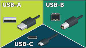
USB
14
DDR4
DDR4 (Double Data Rate 4) is a type of computer memory used in devices like desktops and laptops. It's an improvement over DDR3, offering even faster data transfer rates, increased bandwidth, and better energy efficiency. DDR4 is commonly used in modern systems and provides enhanced performance for various computing tasks. RAM
15
SODIMM
Small Outline Dual In-Line Memory Module (SODIMM) is the best type of random access memory (RAM) module, most likely to be laptop compatible. SODIMM refers to the smaller physical form factor typically used in laptops and mobile devices.
16
DDR2
DDR2 (Double Data Rate 2) is an older type of computer memory used in devices like desktops and laptops. It's a predecessor to DDR3. RAM
17
DDR3 (Double Data Rate 3) is a type of computer memory used in devices like desktops and laptops. Newer then DDR2 older then DDR4.
DDR3
DDR3 (Double Data Rate 3) is a type of computer memory used in devices like desktops and laptops. Newer then DDR2 older then DDR4.
18
DDR4
DDR4 (Double Data Rate 4) is a type of computer memory used in devices like desktops and laptops. Newer then DDR3, offering even faster data transfer rates, increased bandwidth, and better energy efficiency. DDR4 is commonly used in modern systems and provides enhanced performance for various computing tasks. RAM
19
DIMM
DIMM stands for Dual Inline Memory Module. Typically used in desktops and servers. DIMMs are rectangular circuit boards with integrated memory chips that plug into the motherboard.
20
Operating system compatibility.
Motherboard compatibility.
Motherboard compatibility.
You are installing a new internal wireless card in a laptop.
Which of the following considerations is essential when selecting a compatible wireless card?
(Select two.)
Which of the following considerations is essential when selecting a compatible wireless card?
(Select two.)
21
Docking Station
A docking station is a device that allows you to connect your laptop or other portable device to additional peripherals and accessories. It typically provides a simplified way to link your portable device to a set of external devices, such as a monitor, keyboard, mouse, and other accessories. The docking station often uses a single connection to your device, making it easy to dock and undock.
22
Port Replicator
A port replicator is a device that expands the connection options of your laptop. It replicates your laptop's ports and provides extra ones, making it easier to connect multiple peripherals with a single connection. It simplifies the process of docking and connecting various devices to your laptop.
23
GSM
Global System for Mobile Communications (GSM) is a widely used cellular network technology adopted by many carriers worldwide. It is the only technology used in Europe based on a mandate. If your device supports GSM, it will likely be compatible with most GSM technology carriers. GSM is a standard for mobile communication that enables voice and data services, including text messaging and internet access. It operates on specific frequency bands and uses Subscriber Identity Module (SIM) cards to authenticate and identify subscribers.
24
CDMA
Code-Division Multiple Access (CDMA) is a cellular network technology that is less commonly used than GSM. CDMA is primarily utilized by specific carriers in certain regions. While some devices support both GSM and CDMA, compatibility with CDMA networks may vary depending on the device and carrier. CDMA is not supported in Europe.
25
LTE (4G)
LTE (4G)
Long-Term Evolution (LTE) refers to the fourth-generation wireless technology that provides high-speed data connectivity, commonly known as 4G. LTE is an advanced data network that operates alongside GSM or CDMA technologies for cellular communication. While LTE enhances data transfer rates, it is not a primary consideration when evaluating compatibility with network technologies.
26
WIFI
Wireless Fidelity (WiFi) is a wireless networking technology used for local area network (LAN) connectivity. While WiFi enables wireless internet access within a limited range, it is not directly related to cellular network technologies like GSM or CDMA. Set up SSID and Pass
27
PRL
Performing a Preferred Roaming List (PRL) update can help enable network connectivity when traveling to a different country. The PRL is a database on your mobile device that contains information about the carrier networks available for roaming. By updating the PRL, your device can access the updated list of carrier networks in the visited country, increasing the chances of connecting to a compatible network and enabling network services such as calls, text messages, and data.
28
Firmware
Firmware is a type of software that is embedded into hardware devices to control their functionality. It serves as the intermediary between the hardware and higher-level software, providing instructions for how the device should operate. Firmware is stored in non-volatile memory, allowing it to retain its instructions even when the device is powered off.
29
OS
An operating system (OS) is a software program that acts as an intermediary between computer hardware and the computer user. It provides a user interface and manages hardware resources to facilitate the execution of various software applications. The OS plays a crucial role in ensuring that the computer system functions smoothly and that users can interact with it effectively.
30
Driver
In information technology, a driver is a specialized software component that allows an operating system to communicate with and control hardware devices. Drivers act as translators between the high-level commands issued by the operating system and the specific instructions required by the hardware components. They enable the seamless interaction between software and hardware, allowing applications and the operating system to utilize various devices.
31
LCD
• Liquid crystal display - Light shines through liquid crystals
Advantages
• Lightweight
• Relatively low power and relatively inexpensive
Disadvantages
• Black levels are a challenge
• Requires separate backlight
• Florescent, LED, etc. / Difficult to replace
• Changes to native resolution may look
blurry or not as crisp
Advantages
• Lightweight
• Relatively low power and relatively inexpensive
Disadvantages
• Black levels are a challenge
• Requires separate backlight
• Florescent, LED, etc. / Difficult to replace
• Changes to native resolution may look
blurry or not as crisp
32
Mobile Device Batteries
Lithium Ion (Li-ion)
• Common in consumer electronics
• No “memory effect”
• Charging the battery diminishes capacity
Lithium-polymer (Li-poly)
Older Battery, prone to swelling.
• Common in consumer electronics
• No “memory effect”
• Charging the battery diminishes capacity
Lithium-polymer (Li-poly)
Older Battery, prone to swelling.
33
You have just purchased a new Bluetooth headset for your mobile device.
Which steps should you perform to set up and configure the headset?
Which steps should you perform to set up and configure the headset?
Enable Bluetooth on your mobile device, and pair it with the headset.
34
VPN
A VPN, or Virtual Private Network, is a technology that allows you to create a secure and encrypted connection over the internet. It enables users to access a private network, such as their company's internal network, while maintaining privacy and security. VPNs are commonly used for various purposes, including securing internet connections, accessing region-restricted content, and enhancing privacy.
35
You are replacing the keyboard on a laptop.
Which steps should be performed as part of the keyboard replacement process?
(Select three.)
Which steps should be performed as part of the keyboard replacement process?
(Select three.)
Configure the new keyboard.
Ground yourself using an antistatic wrist strap.
Disconnect the ribbon cable from the old keyboard.
Ground yourself using an antistatic wrist strap.
Disconnect the ribbon cable from the old keyboard.
36
Wireless cards, also known as Wi-Fi cards or network adapters, are hardware components that enable computers and other devices to connect to wireless networks. These cards facilitate wireless communication by implementing the IEEE 802.11 standards, allowing devices to establish connections with Wi-Fi routers and access points.
Wireless Cards
Wireless cards, also known as Wi-Fi cards or network adapters, are hardware components that enable computers and other devices to connect to wireless networks. These cards facilitate wireless communication by implementing the IEEE 802.11 standards, allowing devices to establish connections with Wi-Fi routers and access points.
37
Ambient Light Sensor
Sensor: An ambient light sensor detects the surrounding light conditions and adjusts the display brightness accordingly to optimize visibility and save battery.
38
Proximity Sensor
The proximity sensor detects the presence of nearby objects, such as when the phone is brought close to the ear during a call, and can turn off the display to prevent accidental touch inputs.
39
Biometric Sensors
Fingerprint Scanner: Some mobile displays incorporate fingerprint sensors for biometric authentication.
Facial Recognition: Facial recognition sensors use infrared or other technologies to scan and recognize the user's face for unlocking the device.
Facial Recognition: Facial recognition sensors use infrared or other technologies to scan and recognize the user's face for unlocking the device.
40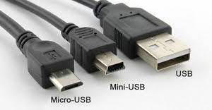
USB TYPES
41
Serial Interfaces
Serial interfaces are communication interfaces that transmit data sequentially, one bit at a time, over a single communication channel. These interfaces are widely used for connecting various devices, peripherals, and components within electronic systems. Unlike parallel interfaces that transmit multiple bits simultaneously over separate channels, serial interfaces use a single channel for transmitting and receiving data.
42
Cellular Location Services
Cellular Network Triangulation:
Cell Towers: Mobile devices communicate with nearby cell towers as part of their normal operation in a cellular network. Each cell tower covers a specific geographic area.
Triangulation: By measuring the signal strength and timing of signals from multiple cell towers, cellular networks can estimate the location of a mobile device through a process known as triangulation. This involves determining the intersection of signal coverage areas.
GPS and A-GPS:
GPS Integration: Many mobile devices have built-in GPS receivers that use signals from GPS satellites to determine precise location.
Assisted GPS (A-GPS): A-GPS enhances the speed and accuracy of GPS by using assistance data from cellular networks. This includes data like satellite ephemeris information and approximate location, helping the GPS receiver acquire a fix more quickly.
Wi-Fi Positioning:
Wi-Fi Access Points: Mobile devices can use Wi-Fi signals from nearby access points to determine location. Wi-Fi positioning relies on a database of Wi-Fi access point locations.
Database Matching: The device scans for nearby Wi-Fi networks, and the collected data is compared against a database to estimate the device's location based on known Wi-Fi access points.
Bluetooth and Beacon Technology:
Bluetooth: Bluetooth signals and beacon technology, such as Bluetooth Low Energy (BLE) beacons, can be used for proximity-based location services, especially in indoor environments.
Beacon Triangulation: Multiple beacons can be strategically placed to triangulate the location of a device within a defined area.
Network-Based Location Services:
Cell ID and Location Area Code (LAC): Cellular networks can provide location estimates based on Cell ID and LAC information. Cell ID identifies a specific cell tower, while LAC identifies the location area.
Geographical Databases: Location-based services can use databases that map Cell ID and LAC information to geographical coordinates.
Emergency Services (E911):
Enhanced 911 (E911): In many regions, cellular carriers are required to provide enhanced location information to emergency services when a user dials emergency numbers (such as 911 in the U.S.).
Phase II E911: Phase II E911 provides more accurate location information, including latitude and longitude, to assist emergency responders.
Location-Based Services (LBS):
Mapping and Navigation: Cellular location services are integral to mapping applications and turn-by-turn navigation on smartphones.
Local Search and Recommendations: Location-based services provide users with information about nearby points of interest, businesses, and services.
Social Media Check-Ins: Platforms like Foursquare and others use location services for users to check in at specific locations and share their whereabouts.
Cell Towers: Mobile devices communicate with nearby cell towers as part of their normal operation in a cellular network. Each cell tower covers a specific geographic area.
Triangulation: By measuring the signal strength and timing of signals from multiple cell towers, cellular networks can estimate the location of a mobile device through a process known as triangulation. This involves determining the intersection of signal coverage areas.
GPS and A-GPS:
GPS Integration: Many mobile devices have built-in GPS receivers that use signals from GPS satellites to determine precise location.
Assisted GPS (A-GPS): A-GPS enhances the speed and accuracy of GPS by using assistance data from cellular networks. This includes data like satellite ephemeris information and approximate location, helping the GPS receiver acquire a fix more quickly.
Wi-Fi Positioning:
Wi-Fi Access Points: Mobile devices can use Wi-Fi signals from nearby access points to determine location. Wi-Fi positioning relies on a database of Wi-Fi access point locations.
Database Matching: The device scans for nearby Wi-Fi networks, and the collected data is compared against a database to estimate the device's location based on known Wi-Fi access points.
Bluetooth and Beacon Technology:
Bluetooth: Bluetooth signals and beacon technology, such as Bluetooth Low Energy (BLE) beacons, can be used for proximity-based location services, especially in indoor environments.
Beacon Triangulation: Multiple beacons can be strategically placed to triangulate the location of a device within a defined area.
Network-Based Location Services:
Cell ID and Location Area Code (LAC): Cellular networks can provide location estimates based on Cell ID and LAC information. Cell ID identifies a specific cell tower, while LAC identifies the location area.
Geographical Databases: Location-based services can use databases that map Cell ID and LAC information to geographical coordinates.
Emergency Services (E911):
Enhanced 911 (E911): In many regions, cellular carriers are required to provide enhanced location information to emergency services when a user dials emergency numbers (such as 911 in the U.S.).
Phase II E911: Phase II E911 provides more accurate location information, including latitude and longitude, to assist emergency responders.
Location-Based Services (LBS):
Mapping and Navigation: Cellular location services are integral to mapping applications and turn-by-turn navigation on smartphones.
Local Search and Recommendations: Location-based services provide users with information about nearby points of interest, businesses, and services.
Social Media Check-Ins: Platforms like Foursquare and others use location services for users to check in at specific locations and share their whereabouts.
43
MDM
MDM stands for Mobile Device Management, and it refers to a set of solutions and technologies designed to manage, secure, and monitor mobile devices (such as smartphones and tablets) within an organization. MDM is particularly important in enterprise settings where there is a need to efficiently manage a fleet of mobile devices used by employees. Here are key aspects of Mobile Device Management:
Device Enrollment:
Provisioning: MDM allows IT administrators to enroll devices into the management system, configuring settings and applying security policies during the provisioning process.
Over-the-Air (OTA) Enrollment: Devices can be enrolled in MDM remotely over the air, streamlining the setup process for end-users.
Configuration Management:
Settings Configuration: MDM enables administrators to configure device settings, including Wi-Fi, email, VPN, and other configuration parameters.
Policy Enforcement: Security policies, such as password requirements and encryption settings, can be enforced through MDM to ensure compliance with organizational security standards.
Security Controls:
Device Security: MDM provides features to enhance device security, such as remote lock and wipe capabilities in case of loss or theft.
Encryption: MDM solutions can enforce encryption settings on devices to protect sensitive data.
Application Management:
App Distribution: MDM allows administrators to manage the distribution of apps to devices, including both enterprise apps and public apps from app stores.
App Configuration: Settings and configurations for specific apps can be managed centrally through MDM.
Monitoring and Reporting:
Device Monitoring: MDM solutions offer monitoring capabilities to track device health, usage patterns, and compliance with policies.
Reporting: Administrators can generate reports on various aspects of device management, including security status, app usage, and compliance metrics.
Remote Support and Troubleshooting:
Remote Assistance: MDM enables IT support teams to provide remote assistance to users, troubleshoot issues, and perform diagnostics.
Remote Control: In certain scenarios, MDM may allow administrators to take remote control of a device for troubleshooting purposes.
Geolocation and Tracking:
Location Tracking: MDM solutions may offer geolocation features to track the location of devices, which can be useful for asset management and security purposes.
Geofencing: Some MDM solutions support geofencing, allowing administrators to define virtual boundaries and trigger actions based on a device's entry or exit from those areas.
Compliance and Policy Enforcement:
Compliance Checks: MDM continuously checks devices for compliance with security policies and takes corrective actions if necessary.
Automated Enforcement: Automated enforcement of policies ensures that devices remain in compliance without manual intervention.
Device Enrollment:
Provisioning: MDM allows IT administrators to enroll devices into the management system, configuring settings and applying security policies during the provisioning process.
Over-the-Air (OTA) Enrollment: Devices can be enrolled in MDM remotely over the air, streamlining the setup process for end-users.
Configuration Management:
Settings Configuration: MDM enables administrators to configure device settings, including Wi-Fi, email, VPN, and other configuration parameters.
Policy Enforcement: Security policies, such as password requirements and encryption settings, can be enforced through MDM to ensure compliance with organizational security standards.
Security Controls:
Device Security: MDM provides features to enhance device security, such as remote lock and wipe capabilities in case of loss or theft.
Encryption: MDM solutions can enforce encryption settings on devices to protect sensitive data.
Application Management:
App Distribution: MDM allows administrators to manage the distribution of apps to devices, including both enterprise apps and public apps from app stores.
App Configuration: Settings and configurations for specific apps can be managed centrally through MDM.
Monitoring and Reporting:
Device Monitoring: MDM solutions offer monitoring capabilities to track device health, usage patterns, and compliance with policies.
Reporting: Administrators can generate reports on various aspects of device management, including security status, app usage, and compliance metrics.
Remote Support and Troubleshooting:
Remote Assistance: MDM enables IT support teams to provide remote assistance to users, troubleshoot issues, and perform diagnostics.
Remote Control: In certain scenarios, MDM may allow administrators to take remote control of a device for troubleshooting purposes.
Geolocation and Tracking:
Location Tracking: MDM solutions may offer geolocation features to track the location of devices, which can be useful for asset management and security purposes.
Geofencing: Some MDM solutions support geofencing, allowing administrators to define virtual boundaries and trigger actions based on a device's entry or exit from those areas.
Compliance and Policy Enforcement:
Compliance Checks: MDM continuously checks devices for compliance with security policies and takes corrective actions if necessary.
Automated Enforcement: Automated enforcement of policies ensures that devices remain in compliance without manual intervention.
44
MAM
MAM stands for Mobile Application Management, and it refers to the set of technologies, processes, and strategies used to manage and secure mobile applications within an organization. While Mobile Device Management (MDM) focuses on the overall management of mobile devices, MAM is specifically concerned with the management of applications and their data on those devices. Here are key aspects of Mobile Application Management:
App Distribution:
App Deployment: MAM allows administrators to deploy, distribute, and manage applications across mobile devices within an organization.
App Catalogs: Organizations can create app catalogs, making it easy for users to discover and install approved applications.
App Configuration:
Settings and Policies: MAM enables administrators to configure settings and policies for specific applications. This may include security settings, feature restrictions, and other configurations.
App Wrapping: Some MAM solutions offer app wrapping, a technique that allows organizations to add an additional layer of security and management to existing applications without modifying their source code.
Security Controls:
Data Protection: MAM solutions focus on securing app data, including measures such as encryption, secure containers, and data loss prevention (DLP) policies.
Access Controls: MAM provides controls for managing user access to apps, ensuring that only authorized users can use certain applications.
App Updates and Patch Management:
Update Management: MAM solutions assist in managing app updates, ensuring that users have access to the latest versions with bug fixes, security patches, and new features.
Patch Deployment: Administrators can deploy patches and updates to applications, addressing vulnerabilities and maintaining a secure application environment.
App Compliance and Reporting:
Compliance Monitoring: MAM monitors apps for compliance with security policies and regulations, taking corrective actions if necessary.
Reporting and Analytics: Administrators can generate reports on app usage, security incidents, and compliance metrics to assess the overall health of the application environment.
App Containerization:
Containerized Apps: Some MAM solutions use app containerization, isolating each app and its data in a secure container. This ensures that the app's data is protected and does not interfere with other apps.
Separation of Work and Personal Data: MAM solutions often provide mechanisms to separate work-related data and applications from personal data on users' devices.
Authentication and Single Sign-On:
Authentication Integration: MAM integrates with authentication systems, enabling single sign-on (SSO) and ensuring that users only need to authenticate once to access multiple apps.
Multi-Factor Authentication (MFA): MAM solutions may support multi-factor authentication for an added layer of security.
Offline Access and Data Sync:
Offline Capabilities: MAM solutions may provide offline access to certain applications, allowing users to work with data even when not connected to the internet.
Data Synchronization: Changes made offline can be synchronized with backend systems when the device is back online.
MAM solutions are especially valuable in enterprise environments where organizations want to ensure the secure and efficient use of mobile applications across various devices. They complement MDM solutions by focusing specifically on the application layer.
App Distribution:
App Deployment: MAM allows administrators to deploy, distribute, and manage applications across mobile devices within an organization.
App Catalogs: Organizations can create app catalogs, making it easy for users to discover and install approved applications.
App Configuration:
Settings and Policies: MAM enables administrators to configure settings and policies for specific applications. This may include security settings, feature restrictions, and other configurations.
App Wrapping: Some MAM solutions offer app wrapping, a technique that allows organizations to add an additional layer of security and management to existing applications without modifying their source code.
Security Controls:
Data Protection: MAM solutions focus on securing app data, including measures such as encryption, secure containers, and data loss prevention (DLP) policies.
Access Controls: MAM provides controls for managing user access to apps, ensuring that only authorized users can use certain applications.
App Updates and Patch Management:
Update Management: MAM solutions assist in managing app updates, ensuring that users have access to the latest versions with bug fixes, security patches, and new features.
Patch Deployment: Administrators can deploy patches and updates to applications, addressing vulnerabilities and maintaining a secure application environment.
App Compliance and Reporting:
Compliance Monitoring: MAM monitors apps for compliance with security policies and regulations, taking corrective actions if necessary.
Reporting and Analytics: Administrators can generate reports on app usage, security incidents, and compliance metrics to assess the overall health of the application environment.
App Containerization:
Containerized Apps: Some MAM solutions use app containerization, isolating each app and its data in a secure container. This ensures that the app's data is protected and does not interfere with other apps.
Separation of Work and Personal Data: MAM solutions often provide mechanisms to separate work-related data and applications from personal data on users' devices.
Authentication and Single Sign-On:
Authentication Integration: MAM integrates with authentication systems, enabling single sign-on (SSO) and ensuring that users only need to authenticate once to access multiple apps.
Multi-Factor Authentication (MFA): MAM solutions may support multi-factor authentication for an added layer of security.
Offline Access and Data Sync:
Offline Capabilities: MAM solutions may provide offline access to certain applications, allowing users to work with data even when not connected to the internet.
Data Synchronization: Changes made offline can be synchronized with backend systems when the device is back online.
MAM solutions are especially valuable in enterprise environments where organizations want to ensure the secure and efficient use of mobile applications across various devices. They complement MDM solutions by focusing specifically on the application layer.
45
Mobile Device Synchronization
Mobile device synchronization refers to the process of ensuring that data on a mobile device is consistent with data on other devices or servers. Synchronization allows users to access the same set of information across multiple devices, ensuring that updates and changes made on one device are reflected on others. Here are key aspects of mobile device synchronization:
Types of Data Synchronization:
Contacts: Synchronization of contact information ensures that phone numbers, email addresses, and other contact details are consistent across devices.
Calendars: Synchronization of calendars enables users to have the same schedule, events, and appointments on all their devices.
Email: Email synchronization ensures that emails, folders, and other mailbox items are mirrored across devices.
Files and Documents: Synchronization of files and documents allows users to access the same set of files on multiple devices, often facilitated through cloud storage services.
App Data: Some applications synchronize data to provide a seamless experience across devices. For example, gaming progress or settings in productivity apps.
Methods of Synchronization:
Cloud Services: Many devices leverage cloud services for synchronization. Data is stored in the cloud, and changes made on one device are reflected in real-time on other connected devices.
Sync Protocols: Synchronization protocols like SyncML, CalDAV, and CardDAV are used for specific types of data synchronization, such as calendars and contacts.
Device-to-Device Sync: In some cases, devices may synchronize directly with each other without using a central server. This is common in peer-to-peer scenarios.
Cable or Wireless Sync: Some devices support synchronization through physical connections (USB cables) or wireless technologies like Bluetooth or Wi-Fi Direct.
Automatic vs. Manual Synchronization:
Automatic Sync: Many devices and applications offer automatic synchronization, where changes are detected and synced in the background without user intervention.
Manual Sync: Users may have the option to initiate synchronization manually, allowing more control over when the data is updated.
Conflict Resolution:
Handling Conflicts: In scenarios where changes are made on multiple devices simultaneously, conflict resolution mechanisms determine how conflicts are resolved. This may involve prioritizing changes based on timestamps or user preferences.
Security and Privacy:
Encryption: Synchronized data is often encrypted during transmission and storage to ensure security.
Privacy Controls: Users may have control over which data is synchronized and with whom, especially when using cloud services.
Cross-Platform Synchronization:
Compatibility: Synchronization solutions aim to be compatible with various platforms, allowing users to sync data between devices running different operating systems (e.g., iOS, Android, Windows).
Third-Party Apps: Some third-party applications specialize in cross-platform synchronization, providing a unified experience across different devices and ecosystems.
Selective Synchronization:
Choosing Data: Users may have the ability to choose specific types of data or folders for synchronization, allowing for more granular control over the synchronized content.
Mobile device synchronization is a fundamental aspect of creating a seamless and integrated user experience across various devices. It enables users to stay up-to-date with their data and ensures consistency, regardless of the device they are using.
Types of Data Synchronization:
Contacts: Synchronization of contact information ensures that phone numbers, email addresses, and other contact details are consistent across devices.
Calendars: Synchronization of calendars enables users to have the same schedule, events, and appointments on all their devices.
Email: Email synchronization ensures that emails, folders, and other mailbox items are mirrored across devices.
Files and Documents: Synchronization of files and documents allows users to access the same set of files on multiple devices, often facilitated through cloud storage services.
App Data: Some applications synchronize data to provide a seamless experience across devices. For example, gaming progress or settings in productivity apps.
Methods of Synchronization:
Cloud Services: Many devices leverage cloud services for synchronization. Data is stored in the cloud, and changes made on one device are reflected in real-time on other connected devices.
Sync Protocols: Synchronization protocols like SyncML, CalDAV, and CardDAV are used for specific types of data synchronization, such as calendars and contacts.
Device-to-Device Sync: In some cases, devices may synchronize directly with each other without using a central server. This is common in peer-to-peer scenarios.
Cable or Wireless Sync: Some devices support synchronization through physical connections (USB cables) or wireless technologies like Bluetooth or Wi-Fi Direct.
Automatic vs. Manual Synchronization:
Automatic Sync: Many devices and applications offer automatic synchronization, where changes are detected and synced in the background without user intervention.
Manual Sync: Users may have the option to initiate synchronization manually, allowing more control over when the data is updated.
Conflict Resolution:
Handling Conflicts: In scenarios where changes are made on multiple devices simultaneously, conflict resolution mechanisms determine how conflicts are resolved. This may involve prioritizing changes based on timestamps or user preferences.
Security and Privacy:
Encryption: Synchronized data is often encrypted during transmission and storage to ensure security.
Privacy Controls: Users may have control over which data is synchronized and with whom, especially when using cloud services.
Cross-Platform Synchronization:
Compatibility: Synchronization solutions aim to be compatible with various platforms, allowing users to sync data between devices running different operating systems (e.g., iOS, Android, Windows).
Third-Party Apps: Some third-party applications specialize in cross-platform synchronization, providing a unified experience across different devices and ecosystems.
Selective Synchronization:
Choosing Data: Users may have the ability to choose specific types of data or folders for synchronization, allowing for more granular control over the synchronized content.
Mobile device synchronization is a fundamental aspect of creating a seamless and integrated user experience across various devices. It enables users to stay up-to-date with their data and ensures consistency, regardless of the device they are using.
46
Truck Example
The truck is owned by (IP) Internet protocol "Address", The Boxes are (TCP) Transmission Control Protocol "Reliable" and (UDP) User Datagram Protocol "Unreliable" delivery, the truck delivers IP to IP, the boxes are labeled to a certain Port "Room" in the recieving IP.
47
FTP
– File Transfer Protocol
• tcp/20 (active mode data) "Actual Delivery", tcp/21 (control) "Hey I got or want something"
• Transfers files between systems
• Authenticates with a username and password
• Some systems use a generic/anonymous login
• Full-featured functionality
• List, add, delete, etc.
• tcp/20 (active mode data) "Actual Delivery", tcp/21 (control) "Hey I got or want something"
• Transfers files between systems
• Authenticates with a username and password
• Some systems use a generic/anonymous login
• Full-featured functionality
• List, add, delete, etc.
48
SSH
Secure Shell • Encrypted communication between IP - tcp/22 CONNECTED
49
Telnet
Telnet – Unencrypted communication Between IP - tcp/23
50
SMTP
- Simple Mail Transfer Protocol
• Server to server email transfer - tcp/25
• Server to server email transfer - tcp/25
51
DNS
- Domain Name System
• Converts names to IP addresses - udp/53
• www.professormesser.com = 162.159.246.164
• Converts names to IP addresses - udp/53
• www.professormesser.com = 162.159.246.164
52
DHCP
Dynamic Host Configuration Protocol CONNECTIONLESS
• Automated configuration of IP address, subnet mask
and other options
• udp/67 Recieves request, udp/68 Sends
Addresses are assigned by MAC address
in the DHCP server
• Quickly manage addresses from one location
• Automated configuration of IP address, subnet mask
and other options
• udp/67 Recieves request, udp/68 Sends
Addresses are assigned by MAC address
in the DHCP server
• Quickly manage addresses from one location
53
MAC
Media Access Control address, is a unique identifier assigned to network interfaces for communications on a network. Think of it as a "serial number" for your device's network connection.
54
HTTP and HTTPS
HTTP Hypertext Transfer Protocol - tcp/80
• Communication in the browser unencrypted CONNECTED
HTTPS Hypertext Transfer Protocol Secure - tcp/443
• Communication in the browser encrypted
• Communication in the browser unencrypted CONNECTED
HTTPS Hypertext Transfer Protocol Secure - tcp/443
• Communication in the browser encrypted
55
POP3
- Post office Protocol version 3 - tcp/110 Unencrypted
• Receieves Email
• Receieves Email
56
NETBIOS
udp/137 NetBIOS name service Register, remove, and find Windows services by name
udp/138 NetBIOS short messaging service Windows connectionless data transfer
tcp/139 NetBIOS a connection for larger messages/data Windows connection-oriented data transfer
udp/138 NetBIOS short messaging service Windows connectionless data transfer
tcp/139 NetBIOS a connection for larger messages/data Windows connection-oriented data transfer
57
IMAP
tcp/143 Internet Message Access Protocol v4 seamless email management across multiple devices.
58
SNMP
SNMP (Simple Network Management Protocol) UDP/161 Monitors network devices and their status. UDP/162 "traps" Notifies of events or issues.
59
LDAP
tcp/389 Lightweight Directory Access Protocol. LDAP is a protocol for accessing and managing directory services, providing a structured and efficient way to store and retrieve information in a networked environment. It's crucial in many organizations for managing user identities and permissions.
60
SMB
tcp/445 Server Message Block Windows file transfers and printer sharing. (CIFS) Common Internet File System
61
RDP
tcp/3389 Remote Desktop Protocol. Graphical display of remote devices
62
TFTP
Trivial File Transfer Protocol, is a simple protocol used for transferring files between devices on a network. UDP/69 CONNECTIONLESS
63
Routers
• Routes traffic between IP subnets
• Makes forwarding decisions based on IP address
• Makes forwarding decisions based on IP address
64
Switches
Bridging done in hardware between accessories.
Unmanaged switches
• Very few configuration options
• Plug and play
• Fixed configuration
• No VLANs
• Very little integration with other devices
• No management protocols
• Low price point
• Simple is less expensive
Managed switches
• VLAN support
• Interconnect with other switches via 802.1Q
• Traffic prioritization
• Voice traffic gets a higher priority
• Redundancy support
• Spanning Tree Protocol (STP)
• External management
• Simple Network Management Protocol (SNMP)
• Port mirroring
• Capture packets
Unmanaged switches
• Very few configuration options
• Plug and play
• Fixed configuration
• No VLANs
• Very little integration with other devices
• No management protocols
• Low price point
• Simple is less expensive
Managed switches
• VLAN support
• Interconnect with other switches via 802.1Q
• Traffic prioritization
• Voice traffic gets a higher priority
• Redundancy support
• Spanning Tree Protocol (STP)
• External management
• Simple Network Management Protocol (SNMP)
• Port mirroring
• Capture packets
65
Access Points
An access point (AP) is a device that allows Wi-Fi-enabled devices to connect to a wired network using Wi-Fi.
66
Patch Panel
A patch panel is a mounted hardware unit that contains ports used to connect and manage the incoming and outgoing network or telecommunications cables.
67
Firewall
A firewall is a protective barrier between your computer or network and the internet. It monitors and controls incoming and outgoing network traffic based on rules. Software and hardware options.
68
PoE
PoE, or Power over Ethernet, is a technology that enables both data and electrical power to be transmitted over a single Ethernet cable.
PoE injectors enable the transmission of electrical power along with data over a standard Ethernet cable to power PoE-compatible devices.
A PoE (Power over Ethernet) switch is a network switch that has the capability to deliver electrical power along with data over Ethernet cables to connected devices. Here's a simplified explanation
PoE (IEEE 802.3af): Standards
Power Level: Up to 15.4 watts.
Devices: Basic devices like IP cameras and phones.
Voltage: Around 48 volts.
Pairs Used: Two pairs of wires for power.
PoE+ (IEEE 802.3at):
Power Level: Up to 30 watts.
Devices: More powerful devices like high-end cameras and access points.
Voltage: Around 48 volts.
Pairs Used: Two pairs of wires for power.
PoE++ (IEEE 802.3bt):
Power Level: Up to 60 watts (Type 3) and 90 watts (Type 4).
Devices: High-power devices like laptops and advanced cameras.
Voltage: Varies (up to 57 volts for Type 3, up to 100 volts for Type 4).
Pairs Used: All four pairs of wires for power.
Universal PoE (UPOE):
Power Level: Up to 60 watts.
Devices: Cisco's special high-power devices.
Voltage: Around 48 volts.
Pairs Used: Two pairs of wires for power.
4PPoE (4-Pair PoE):
Power Level: Up to 90 watts.
Devices: New standard for very high-power applications.
Voltage: Uses all four pairs of wires for power.
PoE injectors enable the transmission of electrical power along with data over a standard Ethernet cable to power PoE-compatible devices.
A PoE (Power over Ethernet) switch is a network switch that has the capability to deliver electrical power along with data over Ethernet cables to connected devices. Here's a simplified explanation
PoE (IEEE 802.3af): Standards
Power Level: Up to 15.4 watts.
Devices: Basic devices like IP cameras and phones.
Voltage: Around 48 volts.
Pairs Used: Two pairs of wires for power.
PoE+ (IEEE 802.3at):
Power Level: Up to 30 watts.
Devices: More powerful devices like high-end cameras and access points.
Voltage: Around 48 volts.
Pairs Used: Two pairs of wires for power.
PoE++ (IEEE 802.3bt):
Power Level: Up to 60 watts (Type 3) and 90 watts (Type 4).
Devices: High-power devices like laptops and advanced cameras.
Voltage: Varies (up to 57 volts for Type 3, up to 100 volts for Type 4).
Pairs Used: All four pairs of wires for power.
Universal PoE (UPOE):
Power Level: Up to 60 watts.
Devices: Cisco's special high-power devices.
Voltage: Around 48 volts.
Pairs Used: Two pairs of wires for power.
4PPoE (4-Pair PoE):
Power Level: Up to 90 watts.
Devices: New standard for very high-power applications.
Voltage: Uses all four pairs of wires for power.
69
HUB
A hub is a central device that provides a common point for connecting multiple network devices, such as computers, printers, or other devices within a LAN.
70
Cable Modem
A cable modem connects a user's home or business to the internet by using the existing cable television infrastructure.
71
DSL
DSL allows users to connect to the internet using the existing copper telephone lines that are commonly found in homes and businesses.
72
ONT
ONT stands for Optical Network Terminal. It is a key component in a Fiber-to-the-Home (FTTH) or Fiber-to-the-Premises (FTTP) network. Here's a simplified explanation:
Fiber Optic Connection:
An ONT is a device that connects to a fiber optic cable, which carries high-speed data signals using light.
Fiber Optic Connection:
An ONT is a device that connects to a fiber optic cable, which carries high-speed data signals using light.
73
NIC
NIC stands for Network Interface Card. It is a hardware component that allows computers to connect to a network and communicate with other devices. Here's a simplified explanation:
Network Connectivity:
A Network Interface Card (NIC) is a hardware component that provides network connectivity to a computer or other devices.
Network Connectivity:
A Network Interface Card (NIC) is a hardware component that provides network connectivity to a computer or other devices.
74
SDN
SDN stands for Software-Defined Networking. It is an innovative approach to network management that uses software applications to control the behavior of network devices and direct traffic on the network. Here's a simplified explanation:
Centralized Control:
SDN shifts the control of network devices, such as switches and routers, from individual devices to a centralized software controller.
Centralized Control:
SDN shifts the control of network devices, such as switches and routers, from individual devices to a centralized software controller.
75
Frenquencies
Wi-Fi operates in the 2.4 GHz and 5 GHz frequency bands. These bands are divided into channels, and devices communicate using radio waves within these frequency ranges. The 5 GHz band generally offers more channels and less interference.
76
SOHO Router
An all-in-one device
• Modem, router, switch, wireless AP, firewall, etc.
A SOHO router, also known as a home router or small office/home office router, is a networking device designed for use in small office or home office environments. Here's a simplified explanation:
• Modem, router, switch, wireless AP, firewall, etc.
A SOHO router, also known as a home router or small office/home office router, is a networking device designed for use in small office or home office environments. Here's a simplified explanation:
77
802.11
The term "802.11" refers to a set of standards developed by the Institute of Electrical and Electronics Engineers (IEEE) for implementing wireless local area networking (WLAN) communication. These standards define the specifications for wireless networking, and the most common use is in Wi-Fi technology. Here's a simplified explanation:
IEEE Standards:
The "802.11" standards are a set of IEEE standards for implementing wireless local area networking.
Wireless Networking (Wi-Fi):
The 802.11 standards are the foundation for Wi-Fi technology, which allows devices to communicate wirelessly within a local network.
802.11b: Introduced in 1999, providing data rates up to 11 Mbps in the 2.4 GHz frequency band.
802.11a: Also introduced in 1999, operating in the 5 GHz frequency band and offering data rates up to 54 Mbps.
802.11g: Introduced in 2003, supporting data rates up to 54 Mbps in the 2.4 GHz frequency band.
802.11n: Introduced in 2009, offering higher data rates (up to 600 Mbps or more) and improved multiple-input and multiple-output (MIMO) technology.
802.11ac: Introduced in 2013, operating in the 5 GHz frequency band and providing higher data rates, enhanced MIMO, and other improvements.
802.11ax (Wi-Fi 6): Introduced in 2019, designed to improve efficiency in crowded environments, increase data rates, and enhance overall performance.
IEEE Standards:
The "802.11" standards are a set of IEEE standards for implementing wireless local area networking.
Wireless Networking (Wi-Fi):
The 802.11 standards are the foundation for Wi-Fi technology, which allows devices to communicate wirelessly within a local network.
802.11b: Introduced in 1999, providing data rates up to 11 Mbps in the 2.4 GHz frequency band.
802.11a: Also introduced in 1999, operating in the 5 GHz frequency band and offering data rates up to 54 Mbps.
802.11g: Introduced in 2003, supporting data rates up to 54 Mbps in the 2.4 GHz frequency band.
802.11n: Introduced in 2009, offering higher data rates (up to 600 Mbps or more) and improved multiple-input and multiple-output (MIMO) technology.
802.11ac: Introduced in 2013, operating in the 5 GHz frequency band and providing higher data rates, enhanced MIMO, and other improvements.
802.11ax (Wi-Fi 6): Introduced in 2019, designed to improve efficiency in crowded environments, increase data rates, and enhance overall performance.
78
RFID
RFID (Radio-frequency identification)
• It’s everywhere
• Access badges
• Inventory/Assembly line tracking
• Pet/Animal identification
• Anything that needs to be tracked
• Radar technology
• Radio energy transmitted to the tag
• RF powers the tag, ID is transmitted back
• Bidirectional communication
• Some tag formats can be active/powered
• It’s everywhere
• Access badges
• Inventory/Assembly line tracking
• Pet/Animal identification
• Anything that needs to be tracked
• Radar technology
• Radio energy transmitted to the tag
• RF powers the tag, ID is transmitted back
• Bidirectional communication
• Some tag formats can be active/powered
79
File Sharing
Local File Sharing: Sharing files within a local network, often using protocols like SMB (Server Message Block) or NFS (Network File System).
Cloud File Sharing: Storing files on cloud platforms (e.g., Dropbox, Google Drive, OneDrive) and sharing them with others by providing access permissions or generating shareable links.
Peer-to-Peer (P2P) File Sharing: Directly sharing files between individual devices without the need for a centralized server. Examples include BitTorrent.
Cloud File Sharing: Storing files on cloud platforms (e.g., Dropbox, Google Drive, OneDrive) and sharing them with others by providing access permissions or generating shareable links.
Peer-to-Peer (P2P) File Sharing: Directly sharing files between individual devices without the need for a centralized server. Examples include BitTorrent.
80
Syslog
• Standard for message logging
• Diverse systems, consolidated log
• Usually a central logging receiver
• Integrated into the SIEM
• Diverse systems, consolidated log
• Usually a central logging receiver
• Integrated into the SIEM
81
AAA
Authentication, authorization and accounting. which are three key components in network security and access control.
82
Internet Appliances
Internet appliances are purpose-built devices designed for specific functions, and they typically provide a focused set of features.
A SPAM GATEWAY employs advanced filtering techniques to analyze incoming email messages and identify those that are likely to be spam or malicious.
UTM unified threat management - consolidates various security functions into a single platform. These features typically include firewall, antivirus, intrusion detection and prevention, content filtering, VPN (Virtual Private Network), and more.
LOAD BALANCER evenly distribute incoming network traffic across multiple servers or resources. This distribution prevents any single server from becoming overwhelmed, ensuring a balanced workload
A PROXY SERVER acts as an intermediary between client devices (such as computers or smartphones) and other servers on the internet. It facilitates communication by forwarding requests from clients to servers and returning the responses. Proxy servers serve various purposes, including improving performance, enhancing security, and providing anonymity. Here's a simplified explanation:
Request Forwarding:
When a client device sends a request to access a resource on the internet (like a website or file), the request is first sent to the proxy server.
A SPAM GATEWAY employs advanced filtering techniques to analyze incoming email messages and identify those that are likely to be spam or malicious.
UTM unified threat management - consolidates various security functions into a single platform. These features typically include firewall, antivirus, intrusion detection and prevention, content filtering, VPN (Virtual Private Network), and more.
LOAD BALANCER evenly distribute incoming network traffic across multiple servers or resources. This distribution prevents any single server from becoming overwhelmed, ensuring a balanced workload
A PROXY SERVER acts as an intermediary between client devices (such as computers or smartphones) and other servers on the internet. It facilitates communication by forwarding requests from clients to servers and returning the responses. Proxy servers serve various purposes, including improving performance, enhancing security, and providing anonymity. Here's a simplified explanation:
Request Forwarding:
When a client device sends a request to access a resource on the internet (like a website or file), the request is first sent to the proxy server.
83
Legacy Embedded Systems
Embedded systems are specialized computing systems designed to perform dedicated functions within larger devices or systems. They are integrated into various products, such as appliances, industrial machinery, medical devices, and automotive systems.
SCADA, which stands for Supervisory Control and Data Acquisition, is a system used for monitoring and controlling industrial processes, infrastructure, and facilities. It plays a crucial role in various industries, including manufacturing, energy, water treatment, and transportation. Here's a simplified explanation:
SCADA is a control system that gathers data from sensors and devices in real-time and provides a centralized interface for monitoring and managing these processes.
SCADA, which stands for Supervisory Control and Data Acquisition, is a system used for monitoring and controlling industrial processes, infrastructure, and facilities. It plays a crucial role in various industries, including manufacturing, energy, water treatment, and transportation. Here's a simplified explanation:
SCADA is a control system that gathers data from sensors and devices in real-time and provides a centralized interface for monitoring and managing these processes.
84
IoT
The Internet of Things (IoT) refers to a network of interconnected devices, objects, or "things" that communicate and exchange data with each other over the internet. These devices are embedded with sensors, actuators, and other technologies that enable them to collect and share information. Here's a simplified explanation of IoT:
Connected Devices:
IoT involves a wide range of physical devices, from everyday objects to complex industrial machines, that are equipped with sensors and connected to the internet.
Connected Devices:
IoT involves a wide range of physical devices, from everyday objects to complex industrial machines, that are equipped with sensors and connected to the internet.
85
IPv4
IPv4, or Internet Protocol version 4, is the fourth version of the Internet Protocol (IP), the set of rules that govern how data is sent and received over the internet. IPv4 is the most widely used version of IP and has been the foundation for internet communication for many years. Here's a simplified explanation:
IP Addressing:
IPv4 uses a 32-bit addressing scheme, expressed as four sets of numbers separated by dots (e.g., 192.168.1.1). Each set, known as an octet, can have values ranging from 0 to 255.
Address Space:
The 32-bit address space in IPv4 allows for approximately 4.3 billion unique IP addresses. While this was sufficient in the early days of the internet, the growth of connected devices has led to concerns about address exhaustion.
Binary Representation:
IPv4 addresses are represented in binary, with each octet converted into its binary equivalent. For example, the IPv4 address 192.168.1.1 is represented as 11000000.10101000.00000001.00000001 in binary.
Private and Public Addresses:
IPv4 addresses are categorized into private and public addresses. Private addresses are reserved for use within private networks and are not routable on the public internet. Public addresses are assigned to devices accessible from the internet.
Subnetting:
IPv4 allows for subnetting, which involves dividing a larger network into smaller subnetworks. Subnetting helps in optimizing network management and routing.
Protocol Stack:
IPv4 is a fundamental part of the TCP/IP protocol stack, which includes other protocols such as Transmission Control Protocol (TCP) and User Datagram Protocol (UDP). These protocols work together to enable communication over the internet.
Header Format:
IPv4 packets have a header that includes various fields, such as source and destination IP addresses, Time to Live (TTL), protocol type, and checksum. The header provides necessary information for the routing and delivery of data packets.
Network Classes:
IPv4 originally defined three main network classes (Class A, B, and C) based on the size of the network and the number of host addresses required. However, Classless Inter-Domain Routing (CIDR) is now commonly used, allowing for more flexible address assignments.
IPv6 Transition:
Due to the limited number of IPv4 addresses and the growth of the internet, IPv6 (Internet Protocol version 6) was introduced as the successor to IPv4. IPv6 uses a 128-bit addressing scheme and provides an immensely larger address space.
NAT (Network Address Translation):
To address IPv4 address exhaustion, NAT is commonly used to map multiple private addresses to a single public address. This allows devices within a private network to share a common public IP address.
Global Deployment:
IPv4 has been globally deployed for several decades and is still widely used. While IPv6 adoption is increasing, the transition from IPv4 to IPv6 is an ongoing process.
In summary, IPv4 is the foundational protocol that has facilitated communication on the internet for many years. Its addressing scheme, packet format, and role in the TCP/IP protocol stack have been crucial to the development and growth of the internet. However, due to the limited address space, the transition to IPv6 is gradually taking place to meet the demands of a vastly expanded internet.
IP Addressing:
IPv4 uses a 32-bit addressing scheme, expressed as four sets of numbers separated by dots (e.g., 192.168.1.1). Each set, known as an octet, can have values ranging from 0 to 255.
Address Space:
The 32-bit address space in IPv4 allows for approximately 4.3 billion unique IP addresses. While this was sufficient in the early days of the internet, the growth of connected devices has led to concerns about address exhaustion.
Binary Representation:
IPv4 addresses are represented in binary, with each octet converted into its binary equivalent. For example, the IPv4 address 192.168.1.1 is represented as 11000000.10101000.00000001.00000001 in binary.
Private and Public Addresses:
IPv4 addresses are categorized into private and public addresses. Private addresses are reserved for use within private networks and are not routable on the public internet. Public addresses are assigned to devices accessible from the internet.
Subnetting:
IPv4 allows for subnetting, which involves dividing a larger network into smaller subnetworks. Subnetting helps in optimizing network management and routing.
Protocol Stack:
IPv4 is a fundamental part of the TCP/IP protocol stack, which includes other protocols such as Transmission Control Protocol (TCP) and User Datagram Protocol (UDP). These protocols work together to enable communication over the internet.
Header Format:
IPv4 packets have a header that includes various fields, such as source and destination IP addresses, Time to Live (TTL), protocol type, and checksum. The header provides necessary information for the routing and delivery of data packets.
Network Classes:
IPv4 originally defined three main network classes (Class A, B, and C) based on the size of the network and the number of host addresses required. However, Classless Inter-Domain Routing (CIDR) is now commonly used, allowing for more flexible address assignments.
IPv6 Transition:
Due to the limited number of IPv4 addresses and the growth of the internet, IPv6 (Internet Protocol version 6) was introduced as the successor to IPv4. IPv6 uses a 128-bit addressing scheme and provides an immensely larger address space.
NAT (Network Address Translation):
To address IPv4 address exhaustion, NAT is commonly used to map multiple private addresses to a single public address. This allows devices within a private network to share a common public IP address.
Global Deployment:
IPv4 has been globally deployed for several decades and is still widely used. While IPv6 adoption is increasing, the transition from IPv4 to IPv6 is an ongoing process.
In summary, IPv4 is the foundational protocol that has facilitated communication on the internet for many years. Its addressing scheme, packet format, and role in the TCP/IP protocol stack have been crucial to the development and growth of the internet. However, due to the limited address space, the transition to IPv6 is gradually taking place to meet the demands of a vastly expanded internet.
86
IPv6
IPv6, or Internet Protocol version 6, is the most recent version of the Internet Protocol (IP) that is designed to replace its predecessor, IPv4. IPv6 was introduced to address the limitations of IPv4, especially its finite address space. Here's a simplified explanation of IPv6:
Addressing Scheme:
IPv6 uses a 128-bit addressing scheme, offering an immensely larger pool of unique addresses compared to the 32-bit addressing scheme used by IPv4. The longer address length allows for approximately 3.4 x 10^38 unique IPv6 addresses.
Hexadecimal Notation:
IPv6 addresses are represented in hexadecimal notation, with colons separating groups of four hexadecimal digits. For example, an IPv6 address might look like 2001:0db8:85a3:0000:0000:8a2e:0370:7334.
Address Types:
IPv6 defines various types of addresses, including Unicast (one-to-one communication), Multicast (one-to-many communication), and Anycast (communication with the nearest of a group of addresses).
Zero Compression:
IPv6 allows for zero compression, meaning consecutive groups of zeros in an IPv6 address can be represented with a double colon (::). This simplifies the notation and reduces the length of addresses.
Global Unicast Addresses:
Similar to public IPv4 addresses, IPv6 has Global Unicast Addresses that are routable on the public internet. These addresses are globally unique and can be assigned to devices connected to the internet.
Link-Local Addresses:
IPv6 introduces link-local addresses for communication within a single network segment. These addresses are automatically configured and are not routable beyond the local network.
Autoconfiguration:
IPv6 includes built-in support for stateless address autoconfiguration. Devices can automatically configure their IPv6 addresses and other network parameters without the need for DHCP (Dynamic Host Configuration Protocol).
Header Simplification:
The IPv6 header is simplified compared to IPv4, which helps improve efficiency and reduce processing overhead on network devices. Certain functions that were optional in IPv4 are now mandatory in IPv6.
Increased Security:
IPv6 includes features that enhance security, including the mandatory use of IPsec (Internet Protocol Security) for secure communication. IPsec was optional in IPv4 but is integral to IPv6.
Transition Mechanisms:
Transition mechanisms exist to facilitate the coexistence of IPv4 and IPv6 during the migration period. These mechanisms enable communication between devices using different IP versions.
IPv6 Adoption:
While IPv6 adoption has been gradual, it is becoming increasingly important as the number of available IPv4 addresses becomes exhausted. Many organizations and internet service providers are working toward IPv6 implementation.
Backward Compatibility:
IPv6 is designed to be backward compatible with IPv4, allowing devices to communicate using either protocol. Transition mechanisms, such as dual-stack configurations, enable coexistence during the transition period.
In summary, IPv6 is the latest version of the Internet Protocol designed to overcome the limitations of IPv4, particularly its finite address space. With an expanded address range, simplified header structure, and enhanced security features, IPv6 is a crucial part of the internet's future as it continues to evolve and grow.
Addressing Scheme:
IPv6 uses a 128-bit addressing scheme, offering an immensely larger pool of unique addresses compared to the 32-bit addressing scheme used by IPv4. The longer address length allows for approximately 3.4 x 10^38 unique IPv6 addresses.
Hexadecimal Notation:
IPv6 addresses are represented in hexadecimal notation, with colons separating groups of four hexadecimal digits. For example, an IPv6 address might look like 2001:0db8:85a3:0000:0000:8a2e:0370:7334.
Address Types:
IPv6 defines various types of addresses, including Unicast (one-to-one communication), Multicast (one-to-many communication), and Anycast (communication with the nearest of a group of addresses).
Zero Compression:
IPv6 allows for zero compression, meaning consecutive groups of zeros in an IPv6 address can be represented with a double colon (::). This simplifies the notation and reduces the length of addresses.
Global Unicast Addresses:
Similar to public IPv4 addresses, IPv6 has Global Unicast Addresses that are routable on the public internet. These addresses are globally unique and can be assigned to devices connected to the internet.
Link-Local Addresses:
IPv6 introduces link-local addresses for communication within a single network segment. These addresses are automatically configured and are not routable beyond the local network.
Autoconfiguration:
IPv6 includes built-in support for stateless address autoconfiguration. Devices can automatically configure their IPv6 addresses and other network parameters without the need for DHCP (Dynamic Host Configuration Protocol).
Header Simplification:
The IPv6 header is simplified compared to IPv4, which helps improve efficiency and reduce processing overhead on network devices. Certain functions that were optional in IPv4 are now mandatory in IPv6.
Increased Security:
IPv6 includes features that enhance security, including the mandatory use of IPsec (Internet Protocol Security) for secure communication. IPsec was optional in IPv4 but is integral to IPv6.
Transition Mechanisms:
Transition mechanisms exist to facilitate the coexistence of IPv4 and IPv6 during the migration period. These mechanisms enable communication between devices using different IP versions.
IPv6 Adoption:
While IPv6 adoption has been gradual, it is becoming increasingly important as the number of available IPv4 addresses becomes exhausted. Many organizations and internet service providers are working toward IPv6 implementation.
Backward Compatibility:
IPv6 is designed to be backward compatible with IPv4, allowing devices to communicate using either protocol. Transition mechanisms, such as dual-stack configurations, enable coexistence during the transition period.
In summary, IPv6 is the latest version of the Internet Protocol designed to overcome the limitations of IPv4, particularly its finite address space. With an expanded address range, simplified header structure, and enhanced security features, IPv6 is a crucial part of the internet's future as it continues to evolve and grow.
87
APIPA
APIPA stands for Automatic Private IP Addressing. It is a feature in some operating systems that automatically assigns a private IP address to a computer when it is unable to obtain an IP address from a Dynamic Host Configuration Protocol (DHCP) server.
88
Static
often refers to the configuration of certain parameters, such as IP addresses or routes, which remain fixed and do not change dynamically.
89
Dynamic
typically refers to configurations or processes that are flexible, adaptable, and can change automatically or in response to certain conditions.
90
Gateway
refers to a device or a software component that serves as an entry or exit point for data traffic between different networks. Gateways play a crucial role in facilitating communication and data transfer between networks with different protocols, architectures, or communication standards.
91
nslookup
“nslookup” - domain name system lookup. Exp. (nslookup google.com)
(nslookup a google.com) - looks up IPv4
(nslookup aaaa google.com) - looks up IPv6
(nslookup a google.com) - looks up IPv4
(nslookup aaaa google.com) - looks up IPv6
92
MX
MX stands for "Mail Exchange." MX records are DNS resource records that specify the mail servers responsible for receiving email messages on behalf of a domain. These records play a crucial role in the email delivery process. As a user or administrator, you generally manage MX records through your domain registrar or DNS hosting provider's control panel. You can add, modify, or remove MX records as needed to specify the mail servers responsible for handling email for your domain. The exact process may vary depending on your DNS hosting provider.
93
TXT
TXT (text) record is a type of resource record used to associate arbitrary text with a domain. TXT records can contain various information, and their purpose depends on how they are used.
Sender Policy Framework (SPF):
SPF is an email authentication protocol that helps prevent email spoofing. SPF uses TXT records to publish information about the authorized mail servers for a domain. The TXT record contains a list of IP addresses or hostnames allowed to send emails on behalf of the domain.
Example SPF TXT record:
makefile
Copy code
v=spf1 ip4:192.168.1.1 include:_spf.example.com ~all
DomainKeys Identified Mail (DKIM):
DKIM is an email authentication method that allows the sender to digitally sign the email, providing a way for the recipient to verify that the email was indeed sent by the domain it claims to be from. The public key used for DKIM verification is often published in a TXT record.
Example DKIM TXT record:
css
Copy code
v=DKIM1; k=rsa; p=MIGfMA0GCSqGSIb3DQEBAQUAA4GNADCBiQKBgQC2...
Domain-based Message Authentication, Reporting, and Conformance (DMARC):
DMARC is a protocol that builds on SPF and DKIM to provide additional email authentication and reporting. It uses TXT records to publish DMARC policies.
Example DMARC TXT record:
css
Copy code
v=DMARC1; p=reject; rua=mailto:postmaster@example.com; ruf=mailto:abuse@example.com
Verification Records:
TXT records are sometimes used for domain ownership verification, especially when setting up services like Google Workspace or Microsoft 365. The service provider may ask you to add a specific TXT record to your domain's DNS as part of the verification process.
Example verification TXT record:
Copy code
google-site-verification=AbCdEfGhIjK1aB2c3DeF4gH5iJ6kL7mN8oP9qR0sT1uV2wX3yZ4
Sender Policy Framework (SPF):
SPF is an email authentication protocol that helps prevent email spoofing. SPF uses TXT records to publish information about the authorized mail servers for a domain. The TXT record contains a list of IP addresses or hostnames allowed to send emails on behalf of the domain.
Example SPF TXT record:
makefile
Copy code
v=spf1 ip4:192.168.1.1 include:_spf.example.com ~all
DomainKeys Identified Mail (DKIM):
DKIM is an email authentication method that allows the sender to digitally sign the email, providing a way for the recipient to verify that the email was indeed sent by the domain it claims to be from. The public key used for DKIM verification is often published in a TXT record.
Example DKIM TXT record:
css
Copy code
v=DKIM1; k=rsa; p=MIGfMA0GCSqGSIb3DQEBAQUAA4GNADCBiQKBgQC2...
Domain-based Message Authentication, Reporting, and Conformance (DMARC):
DMARC is a protocol that builds on SPF and DKIM to provide additional email authentication and reporting. It uses TXT records to publish DMARC policies.
Example DMARC TXT record:
css
Copy code
v=DMARC1; p=reject; rua=mailto:postmaster@example.com; ruf=mailto:abuse@example.com
Verification Records:
TXT records are sometimes used for domain ownership verification, especially when setting up services like Google Workspace or Microsoft 365. The service provider may ask you to add a specific TXT record to your domain's DNS as part of the verification process.
Example verification TXT record:
Copy code
google-site-verification=AbCdEfGhIjK1aB2c3DeF4gH5iJ6kL7mN8oP9qR0sT1uV2wX3yZ4
94
DHCP
DHCP stands for Dynamic Host Configuration Protocol. It is a network protocol used to automatically assign IP addresses and other configuration information to devices on a network. DHCP simplifies the process of configuring devices on a network by dynamically assigning IP addresses, subnet masks, gateways, and other parameters without manual intervention.
The LEASE duration is the amount of time that a DHCP client is allowed to use the assigned IP address. It is specified by the DHCP server when it responds to the client's request.
DHCP RESERVATIONS are commonly used for devices that require a stable and known IP address within the network. This can include servers, printers, network-attached storage (NAS) devices, and other equipment where a consistent IP address is beneficial for network management or service accessibility.
A DHCP SCOPE includes a specified range of IP addresses. For example, a scope might include the range from 192.168.1.100 to 192.168.1.200.
The LEASE duration is the amount of time that a DHCP client is allowed to use the assigned IP address. It is specified by the DHCP server when it responds to the client's request.
DHCP RESERVATIONS are commonly used for devices that require a stable and known IP address within the network. This can include servers, printers, network-attached storage (NAS) devices, and other equipment where a consistent IP address is beneficial for network management or service accessibility.
A DHCP SCOPE includes a specified range of IP addresses. For example, a scope might include the range from 192.168.1.100 to 192.168.1.200.
95
VLAN
A VLAN, or Virtual Local Area Network, is a network technology that allows network administrators to create logically segmented networks within a physical network. VLANs provide a way to group devices together based on factors such as function, department, or team, even if they are physically dispersed across different locations or connected to different network switches.
96
VPN
VPN stands for Virtual Private Network. It is a technology that allows users to create a secure and encrypted connection to a private network over the internet. VPNs are commonly used to enhance privacy and security when accessing the internet, especially when connecting to public Wi-Fi networks or accessing sensitive information.
97
Satallite
Satellite Internet is a type of internet connection that uses satellite technology to provide broadband access. It is particularly useful in areas where traditional broadband options like DSL, cable, or fiber-optic connections may not be available or are impractical.
98
FIBER
Fiber internet, also known as fiber-optic internet, is a high-speed broadband internet connection that uses fiber-optic cables to transmit data. This technology leverages the properties of light to transmit data over thin strands of glass or plastic fibers, providing faster and more reliable internet connectivity compared to traditional copper-based connections.
99
CABLE
Cable internet is a high-speed broadband internet connection that uses cable television infrastructure to deliver data. It utilizes the same coaxial cables that transmit cable television signals to provide internet access.
100
DSL
DSL, which stands for Digital Subscriber Line, is a type of broadband internet connection that uses existing telephone lines to provide high-speed internet access. It is a popular alternative to dial-up connections and offers faster speeds for both downloading and uploading data.
101
Cellular
Cellular internet connection, often referred to as mobile broadband or mobile internet, allows users to access the internet using cellular networks. It enables internet connectivity on mobile devices such as smartphones, tablets, and mobile hotspots.
102
WISP
WISP, or Wireless Internet Service Provider, refers to a type of internet service where internet access is provided wirelessly to customers through radio signals. WISPs typically use fixed wireless technology to deliver internet connectivity to homes and businesses in areas where traditional wired broadband options may be limited or unavailable.
103
LAN
LAN stands for Local Area Network. It is a network of interconnected computers and devices within a limited geographic area, such as a home, office, or campus. LANs facilitate communication and resource sharing among connected devices.
104
WAN
WAN stands for Wide Area Network. It is a type of computer network that covers a broad area, connecting multiple LANs (Local Area Networks) over long distances. WANs are used to enable communication and data exchange between geographically dispersed locations, such as different offices, branches, or data centers.
105
PAN
"PAN" typically stands for Personal Area Network, which is a type of network with a very limited geographic scope, often centered around an individual person and their personal devices. A PAN is usually designed for personal and private connections between devices, such as smartphones, laptops, tablets, and other gadgets.
106
MAN
Metropolitan Area Network. A Metropolitan Area Network is a type of network that covers a larger geographical area than a Local Area Network (LAN) but is smaller than a Wide Area Network (WAN). MANs typically cover a city or a large campus.
107
SAN
Storage Area Network. A Storage Area Network is a specialized high-speed network that provides access to consolidated, block-level data storage. SANs are designed to enhance storage efficiency, performance, and scalability for organizations with large amounts of data.
108
WLAN
Wireless Local Area Network. It is a type of local area network (LAN) that uses wireless communication to connect devices within a limited geographic area, such as a home, office, or campus. WLANs provide the flexibility of wireless connectivity, allowing devices to communicate with each other and access network resources without the need for physical cables.
109
Crimper
110
Stripper
111
Wifi analyzer
A Wi-Fi analyzer is a tool or software application designed to analyze, monitor, and troubleshoot Wi-Fi networks. It provides information about the wireless networks in the vicinity, including details about signal strength, channel usage, interference, and other relevant parameters. Wi-Fi analyzers are commonly used by IT professionals, network administrators, and individuals to optimize Wi-Fi performance and troubleshoot connectivity issues.
112
Toner Probe
A toner probe, also known as a cable tracer or toner and probe kit, is a tool used in network and cabling installations for identifying and tracing cables. It consists of two components: a toner and a probe.
The toner is a handheld device that sends a unique tone or signal along the cable being tested. It is typically connected to one end of the cable or wire. The tone generated by the toner helps in identifying and tracing the specific cable in a bundle or network.
Probe:
The probe is another handheld device with a receiver or sensor. It is used to detect the toner's signal along the length of the cable. The probe is moved along the cables or connectors, and when it comes close to the cable carrying the tone, it produces an audible or visual indication.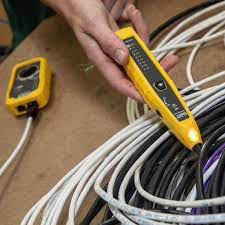
The toner is a handheld device that sends a unique tone or signal along the cable being tested. It is typically connected to one end of the cable or wire. The tone generated by the toner helps in identifying and tracing the specific cable in a bundle or network.
Probe:
The probe is another handheld device with a receiver or sensor. It is used to detect the toner's signal along the length of the cable. The probe is moved along the cables or connectors, and when it comes close to the cable carrying the tone, it produces an audible or visual indication.
113
Punch Down Tool and Block
A punch-down tool, also known as a punch-down tool or krone tool, is a hand tool used in the installation and maintenance of network cabling, particularly for structured cabling systems. It is commonly used with punch-down blocks, patch panels, and keystone jacks. The primary purpose of a punch-down tool is to terminate or "punch down" the individual wires of twisted pair cables into the corresponding terminals on a connector or termination block.
Terminating Wires:
The main function of a punch-down tool is to terminate the individual wires of twisted pair cables into the appropriate slots on connectors or termination blocks. This is a common practice in networking for creating secure and reliable connections.
110 and 66 Blocks:
Punch-down tools are often designed for use with 110 blocks or 66 blocks. These are types of punch-down blocks commonly used in telecommunications and networking for terminating twisted pair cables.
Keystone Jacks:
In structured cabling systems, keystone jacks are commonly used for terminating Ethernet cables. Punch-down tools are used to secure the wires into the designated slots on the keystone jack, ensuring proper electrical contact.
Patch Panels:
Network patch panels, which serve as centralized points for connecting and managing multiple network cables, often require the use of punch-down tools. The tool is used to punch down the individual wires onto the terminals of the patch panel.
Color-Coded Blades:
Many punch-down tools have color-coded blades or tips to correspond with the color-coding of the wires in twisted pair cables. This makes it easier for technicians to match and terminate the correct wire pairs.
Impact Mechanism:
The punch-down tool typically features an impact mechanism. When pressure is applied to the tool, it activates the impact force, ensuring a secure and consistent termination of the wire into the connector or block.
Adjustable Impact Force:
Some punch-down tools allow users to adjust the impact force. This feature is useful for accommodating different cable types and ensuring proper termination without causing damage.
Non-Impact or Punch-and-Cut Tools:
There are non-impact punch-down tools and punch-and-cut tools. Non-impact tools require a separate cutting tool to trim excess wire, while punch-and-cut tools have built-in blades for both punching down and cutting the wire.
Cable Management:
Using punch-down tools ensures proper cable management and organization in structured cabling systems. It helps create neat and reliable connections, reducing the risk of signal interference.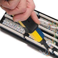
Terminating Wires:
The main function of a punch-down tool is to terminate the individual wires of twisted pair cables into the appropriate slots on connectors or termination blocks. This is a common practice in networking for creating secure and reliable connections.
110 and 66 Blocks:
Punch-down tools are often designed for use with 110 blocks or 66 blocks. These are types of punch-down blocks commonly used in telecommunications and networking for terminating twisted pair cables.
Keystone Jacks:
In structured cabling systems, keystone jacks are commonly used for terminating Ethernet cables. Punch-down tools are used to secure the wires into the designated slots on the keystone jack, ensuring proper electrical contact.
Patch Panels:
Network patch panels, which serve as centralized points for connecting and managing multiple network cables, often require the use of punch-down tools. The tool is used to punch down the individual wires onto the terminals of the patch panel.
Color-Coded Blades:
Many punch-down tools have color-coded blades or tips to correspond with the color-coding of the wires in twisted pair cables. This makes it easier for technicians to match and terminate the correct wire pairs.
Impact Mechanism:
The punch-down tool typically features an impact mechanism. When pressure is applied to the tool, it activates the impact force, ensuring a secure and consistent termination of the wire into the connector or block.
Adjustable Impact Force:
Some punch-down tools allow users to adjust the impact force. This feature is useful for accommodating different cable types and ensuring proper termination without causing damage.
Non-Impact or Punch-and-Cut Tools:
There are non-impact punch-down tools and punch-and-cut tools. Non-impact tools require a separate cutting tool to trim excess wire, while punch-and-cut tools have built-in blades for both punching down and cutting the wire.
Cable Management:
Using punch-down tools ensures proper cable management and organization in structured cabling systems. It helps create neat and reliable connections, reducing the risk of signal interference.
114
Cable Tester
A cable tester is a tool used to verify the integrity and connectivity of network or communication cables. It is commonly used in the installation, maintenance, and troubleshooting of various types of cables, including Ethernet cables (Cat5e, Cat6, Cat6a), coaxial cables, and telephone cables. Cable testers help ensure that cables are properly terminated, wired, and capable of carrying signals without issues.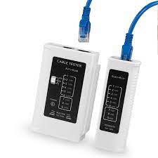
115
Using a loopback plug involves connecting the plug to a network interface, cable, or device to create a loopback path for testing and diagnostics. The exact steps may vary slightly depending on the type of loopback plug and the specific testing scenario.
Identify the Loopback Plug:
Ensure you have the correct loopback plug for your testing needs. Ethernet loopback plugs are designed for testing Ethernet ports.
Turn Off the Device:
Power off the device with the Ethernet port you want to test. This could be a computer, router, switch, or any other network-enabled device.
Insert the Loopback Plug:
Insert the loopback plug into the Ethernet port you want to test. Make sure it is securely connected.
Power On the Device:
Power on the device. The loopback plug will create a closed loop, allowing signals to be sent from the output of the device and looped back to its input.
Check for Connectivity:
Once the device is powered on, check for connectivity. You can use network diagnostic tools or check the device's network settings to see if the Ethernet port is functioning correctly.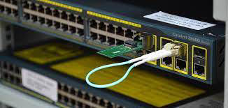
Loopback Plug
Using a loopback plug involves connecting the plug to a network interface, cable, or device to create a loopback path for testing and diagnostics. The exact steps may vary slightly depending on the type of loopback plug and the specific testing scenario.
Identify the Loopback Plug:
Ensure you have the correct loopback plug for your testing needs. Ethernet loopback plugs are designed for testing Ethernet ports.
Turn Off the Device:
Power off the device with the Ethernet port you want to test. This could be a computer, router, switch, or any other network-enabled device.
Insert the Loopback Plug:
Insert the loopback plug into the Ethernet port you want to test. Make sure it is securely connected.
Power On the Device:
Power on the device. The loopback plug will create a closed loop, allowing signals to be sent from the output of the device and looped back to its input.
Check for Connectivity:
Once the device is powered on, check for connectivity. You can use network diagnostic tools or check the device's network settings to see if the Ethernet port is functioning correctly.
116
Network Tap
A network tap is a hardware device that provides a way to monitor and capture network traffic for analysis or security purposes. It allows passive monitoring of the data flowing through a network by copying the traffic from one or more network links. Network taps are commonly used in cybersecurity, network troubleshooting, and performance monitoring.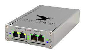
117
CAT Cables - Copper
Key Differences:
Data Rate:
CAT5: Up to 100 Mbps
CAT5e: Up to 1 Gbps
CAT6: Up to 10 Gbps
CAT6a: Up to 10 Gbps (and potentially higher)
Maximum Frequency:
CAT5: 100 MHz
CAT5e: 100 MHz
CAT6: 250 MHz
CAT6a: 500 MHz
Performance and Crosstalk:
Each category is an improvement over the previous one in terms of reducing crosstalk and improving overall performance.
Applications:
CAT5 and CAT5e are suitable for basic networking needs and Fast Ethernet. CAT6 is commonly used for Gigabit Ethernet, and CAT6a is recommended for 10-Gigabit Ethernet and potentially higher data rate applications.
Shielding:
CAT6a cables often come with additional shielding to minimize electromagnetic interference (EMI) and crosstalk.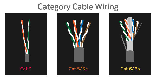
Data Rate:
CAT5: Up to 100 Mbps
CAT5e: Up to 1 Gbps
CAT6: Up to 10 Gbps
CAT6a: Up to 10 Gbps (and potentially higher)
Maximum Frequency:
CAT5: 100 MHz
CAT5e: 100 MHz
CAT6: 250 MHz
CAT6a: 500 MHz
Performance and Crosstalk:
Each category is an improvement over the previous one in terms of reducing crosstalk and improving overall performance.
Applications:
CAT5 and CAT5e are suitable for basic networking needs and Fast Ethernet. CAT6 is commonly used for Gigabit Ethernet, and CAT6a is recommended for 10-Gigabit Ethernet and potentially higher data rate applications.
Shielding:
CAT6a cables often come with additional shielding to minimize electromagnetic interference (EMI) and crosstalk.
118
Coaxial Cable 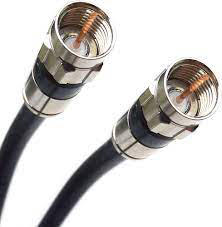
Coaxial cable, often referred to as coax cable, is a type of electrical cable that consists of a central conductor, an insulating layer, a metallic shield, and an outer insulating layer. It is widely used for transmitting cable television signals, internet connectivity, and other data communications. Coaxial cables are known for their ability to carry high-frequency signals with minimal signal loss.
RG-6:
RG-6 coaxial cable is commonly used for cable television (CATV) and satellite television installations. It has a larger diameter and lower signal loss, making it suitable for longer cable runs.
RG-59:
RG-59 coaxial cable is an older standard often used for short cable runs. It is suitable for analog video signals but may have higher signal loss compared to RG-6.
RG-11:
RG-11 is a thicker and heavier coaxial cable that offers even lower signal loss over longer distances. It is commonly used for high-frequency applications, such as long-distance cable TV and internet installations.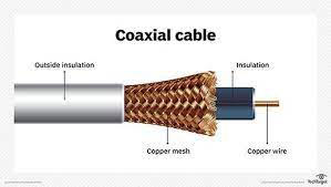
RG-6:
RG-6 coaxial cable is commonly used for cable television (CATV) and satellite television installations. It has a larger diameter and lower signal loss, making it suitable for longer cable runs.
RG-59:
RG-59 coaxial cable is an older standard often used for short cable runs. It is suitable for analog video signals but may have higher signal loss compared to RG-6.
RG-11:
RG-11 is a thicker and heavier coaxial cable that offers even lower signal loss over longer distances. It is commonly used for high-frequency applications, such as long-distance cable TV and internet installations.
119
STP
Shielded twisted pair (STP) is a type of twisted pair cable that includes additional shielding to protect the transmitted signals from electromagnetic interference (EMI) and radio frequency interference (RFI). It is commonly used in environments where there is a higher risk of interference that could impact the performance of the data transmission.
Industrial Environments:
STP cables are commonly used in industrial environments where electrical noise and interference are prevalent.
Hospitals and Healthcare Facilities:
In healthcare settings, where sensitive equipment and electronic devices are in use, STP cables may be preferred.
Government and Military Installations:
Due to the enhanced security and protection against interference, STP cables are used in government and military applications.
Data Centers:
In data centers where high-density installations and high data rates are common, STP cables may be chosen for specific applications.
Industrial Environments:
STP cables are commonly used in industrial environments where electrical noise and interference are prevalent.
Hospitals and Healthcare Facilities:
In healthcare settings, where sensitive equipment and electronic devices are in use, STP cables may be preferred.
Government and Military Installations:
Due to the enhanced security and protection against interference, STP cables are used in government and military applications.
Data Centers:
In data centers where high-density installations and high data rates are common, STP cables may be chosen for specific applications.
120
UDP
UTP stands for Unshielded Twisted Pair, and it refers to a type of copper cabling that is widely used for networking and telecommunications. UTP cables consist of pairs of insulated copper wires twisted together. The twisting of the pairs helps to reduce electromagnetic interference (EMI) and crosstalk between adjacent pairs, making UTP cables suitable for transmitting data reliably.
Ethernet Networking:
UTP cables are the primary choice for Ethernet networking in homes, offices, and data centers.
Telephony:
Used for telephone systems, connecting telephones to wall outlets.
Structured Cabling Systems:
Forms the basis of structured cabling systems in buildings, providing a flexible and standardized approach to cabling.
Data Centers:
UTP cables are used for connecting servers, switches, and other networking equipment within data centers.
Home Networking:
Commonly used for home networking applications, connecting computers, routers, and other devices.
Surveillance Systems:
UTP cables may be used in surveillance systems to connect IP cameras to network recorders.
Ethernet Networking:
UTP cables are the primary choice for Ethernet networking in homes, offices, and data centers.
Telephony:
Used for telephone systems, connecting telephones to wall outlets.
Structured Cabling Systems:
Forms the basis of structured cabling systems in buildings, providing a flexible and standardized approach to cabling.
Data Centers:
UTP cables are used for connecting servers, switches, and other networking equipment within data centers.
Home Networking:
Commonly used for home networking applications, connecting computers, routers, and other devices.
Surveillance Systems:
UTP cables may be used in surveillance systems to connect IP cameras to network recorders.
121
Direct Burial
Direct burial cables can be available in both Unshielded Twisted Pair (UTP) and Shielded Twisted Pair (STP) configurations. The shielding in STP cables provides additional protection against electromagnetic interference (EMI) and radio frequency interference (RFI). While UTP cables do not have the added shielding, direct burial versions of both UTP and STP cables are designed to withstand outdoor conditions and burial in the ground without the need for conduit.
Here's a breakdown of both types:
Direct Burial UTP (DB-UTP):
Direct burial UTP cables are designed for outdoor applications where the cable will be buried directly in the ground. They are constructed with materials that provide resistance to moisture, UV rays, and other environmental factors. The lack of shielding makes them more susceptible to certain types of interference, but they are still suitable for many outdoor scenarios.
Direct Burial STP (DB-STP):
Direct burial STP cables have the same outdoor and burial characteristics as UTP, but they include additional shielding to enhance protection against EMI and RFI. The shielding can be made of foil or braided strands of metal. This makes direct burial STP cables suitable for environments where there is a higher risk of electromagnetic interference.
Here's a breakdown of both types:
Direct Burial UTP (DB-UTP):
Direct burial UTP cables are designed for outdoor applications where the cable will be buried directly in the ground. They are constructed with materials that provide resistance to moisture, UV rays, and other environmental factors. The lack of shielding makes them more susceptible to certain types of interference, but they are still suitable for many outdoor scenarios.
Direct Burial STP (DB-STP):
Direct burial STP cables have the same outdoor and burial characteristics as UTP, but they include additional shielding to enhance protection against EMI and RFI. The shielding can be made of foil or braided strands of metal. This makes direct burial STP cables suitable for environments where there is a higher risk of electromagnetic interference.
122
Plenum
In buildings, the plenum is a space used for air handling and ventilation. It can include areas above suspended ceilings, below raised floors, and other spaces used for HVAC (Heating, Ventilation, and Air Conditioning) systems. The purpose of the plenum space is to facilitate the circulation of air throughout the building.
Plenum cables are specifically designed for use in plenum spaces. These cables have insulation and jackets made from materials that comply with fire safety regulations for plenum areas. Plenum-rated cables are designed to limit the spread of fire and produce minimal smoke in the event of a fire.
Plenum cables are specifically designed for use in plenum spaces. These cables have insulation and jackets made from materials that comply with fire safety regulations for plenum areas. Plenum-rated cables are designed to limit the spread of fire and produce minimal smoke in the event of a fire.
123
Optical Cable / Fiber Optic
An optical cable, also known as a fiber optic cable, is a type of cable that transmits data using light signals through optical fibers made of glass or plastic. Optical cables are widely used in telecommunications, networking, and various data transmission applications.
Single-Mode Fiber (SMF):
Designed for long-distance transmission, single-mode fibers allow a single mode of light to propagate through the core. They are commonly used in telecommunications and long-haul network connections.
Multi-Mode Fiber (MMF):
Multi-mode fibers support the propagation of multiple modes of light through the core. They are suitable for shorter-distance applications, such as local area networks (LANs) and data center connections.
Plenum and Riser Cables:
Optical cables can be categorized based on their fire rating and intended installation environment. Plenum-rated cables are suitable for plenum spaces, while riser-rated cables are designed for vertical installations.
Armored Fiber Cables:
Armored fiber cables have additional layers of protection, such as metal armor, to enhance durability and resistance to physical damage.
Single-Mode Fiber (SMF):
Designed for long-distance transmission, single-mode fibers allow a single mode of light to propagate through the core. They are commonly used in telecommunications and long-haul network connections.
Multi-Mode Fiber (MMF):
Multi-mode fibers support the propagation of multiple modes of light through the core. They are suitable for shorter-distance applications, such as local area networks (LANs) and data center connections.
Plenum and Riser Cables:
Optical cables can be categorized based on their fire rating and intended installation environment. Plenum-rated cables are suitable for plenum spaces, while riser-rated cables are designed for vertical installations.
Armored Fiber Cables:
Armored fiber cables have additional layers of protection, such as metal armor, to enhance durability and resistance to physical damage.
124
Fiber Optic Connectors
ST Connector (Straight Tip Connector):
Bayonet-style connector commonly used in networking applications.
SC Connector (Subscriber Connector or Square Connector):
Square-shaped connector with a push-pull coupling mechanism, widely used in data communications.
LC Connector (Lucent Connector):
Small form factor connector with a 1.25mm ceramic ferrule, commonly used in data center environments.
MTP/MPO Connector (Multiple-Fiber Push-On/Pull-Off Connector):
Connector designed for high-density applications where multiple fibers need to be connected, often used in data center environments.
FC (Ferrule Connector) is indeed a type of fiber optic connector. The FC connector is characterized by its threaded coupling mechanism and a cylindrical ferrule. It is commonly used in telecommunications and networking applications. The FC connector provides a stable and secure connection and is known for its reliability.
Bayonet-style connector commonly used in networking applications.
SC Connector (Subscriber Connector or Square Connector):
Square-shaped connector with a push-pull coupling mechanism, widely used in data communications.
LC Connector (Lucent Connector):
Small form factor connector with a 1.25mm ceramic ferrule, commonly used in data center environments.
MTP/MPO Connector (Multiple-Fiber Push-On/Pull-Off Connector):
Connector designed for high-density applications where multiple fibers need to be connected, often used in data center environments.
FC (Ferrule Connector) is indeed a type of fiber optic connector. The FC connector is characterized by its threaded coupling mechanism and a cylindrical ferrule. It is commonly used in telecommunications and networking applications. The FC connector provides a stable and secure connection and is known for its reliability.
125
RJ45
T568A and T568B are two wiring standards used for terminating twisted pair cables, particularly in Ethernet and other networking applications. These standards define the arrangement of the color-coded wires within an Ethernet cable's connector, ensuring consistency and compatibility in network installations. Both standards specify the order in which the individual wires should be terminated on an RJ45 (Registered Jack 45) connector.
T568A and T568B are specifically designed for terminating twisted pair cables, such as Cat5e, Cat6, and Cat6a cables. T568B is more commonly used in commercial and enterprise environments, while T568A may be found more frequently in residential installations. However, both standards are suitable for various applications
In summary, T568A and T568B are wiring standards that define the order of the color-coded wires within an Ethernet cable's connector. The choice between T568A and T568B often depends on the specific standards adopted within an organization or industry. Consistency in wiring standards is essential for maintaining reliable and compatible network connections.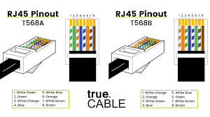
T568A and T568B are specifically designed for terminating twisted pair cables, such as Cat5e, Cat6, and Cat6a cables. T568B is more commonly used in commercial and enterprise environments, while T568A may be found more frequently in residential installations. However, both standards are suitable for various applications
In summary, T568A and T568B are wiring standards that define the order of the color-coded wires within an Ethernet cable's connector. The choice between T568A and T568B often depends on the specific standards adopted within an organization or industry. Consistency in wiring standards is essential for maintaining reliable and compatible network connections.
126
USB 2.0 and 3.0 Perpheral Cable
USB 2.0:
Commonly used for connecting peripherals such as keyboards, mice, printers, and older external storage devices.
USB 3.0:
Suited for high-speed data transfer applications, such as connecting external hard drives, SSDs, and other devices that benefit from faster transfer rates.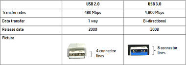
Commonly used for connecting peripherals such as keyboards, mice, printers, and older external storage devices.
USB 3.0:
Suited for high-speed data transfer applications, such as connecting external hard drives, SSDs, and other devices that benefit from faster transfer rates.
127
Serial Cables
RS-232 Standard:
RS-232 is a standard for serial communication that defines the electrical characteristics of signals, connectors, and protocols. It is commonly used for connecting devices such as modems, printers, scanners, and other peripherals to a computer.
Connectors:
RS-232 cables typically use DB9 (9-pin) or DB25 (25-pin) connectors. DB9 connectors are more common in modern devices. Understanding the pin layout of these connectors is important.
Cable Wiring:
RS-232 cables have specific pin assignments for transmit (TX), receive (RX), ground (GND), and other signals. It's essential to know the wiring configurations for both DB9 and DB25 connectors. Some common pin assignments include:
Pin 2: Transmit (TX)
Pin 3: Receive (RX)
Pin 5: Ground (GND)
Null Modem Cables:
Null modem cables are used for direct communication between two devices without the need for a modem in between. These cables often involve crossover wiring, where transmit on one end connects to receive on the other end and vice versa.
Serial Port Settings:
Understanding serial port settings, such as baud rate, data bits, stop bits, and parity, is crucial. These settings need to be configured correctly on both ends of the serial connection for proper communication.
Serial to USB Adapters:
In modern computing environments where serial ports are less common, serial to USB adapters are often used. These adapters convert the serial signal to a USB signal, allowing older serial devices to connect to USB ports on computers.
Troubleshooting Serial Connections:
Knowledge of common issues and troubleshooting steps for serial connections is valuable. This may include checking cable connections, verifying settings, and using loopback tests.
Serial Device Identification:
Being able to identify devices that commonly use serial connections, such as printers, scanners, and modems, is essential for troubleshooting and connectivity.
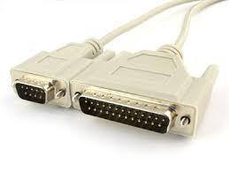
RS-232 is a standard for serial communication that defines the electrical characteristics of signals, connectors, and protocols. It is commonly used for connecting devices such as modems, printers, scanners, and other peripherals to a computer.
Connectors:
RS-232 cables typically use DB9 (9-pin) or DB25 (25-pin) connectors. DB9 connectors are more common in modern devices. Understanding the pin layout of these connectors is important.
Cable Wiring:
RS-232 cables have specific pin assignments for transmit (TX), receive (RX), ground (GND), and other signals. It's essential to know the wiring configurations for both DB9 and DB25 connectors. Some common pin assignments include:
Pin 2: Transmit (TX)
Pin 3: Receive (RX)
Pin 5: Ground (GND)
Null Modem Cables:
Null modem cables are used for direct communication between two devices without the need for a modem in between. These cables often involve crossover wiring, where transmit on one end connects to receive on the other end and vice versa.
Serial Port Settings:
Understanding serial port settings, such as baud rate, data bits, stop bits, and parity, is crucial. These settings need to be configured correctly on both ends of the serial connection for proper communication.
Serial to USB Adapters:
In modern computing environments where serial ports are less common, serial to USB adapters are often used. These adapters convert the serial signal to a USB signal, allowing older serial devices to connect to USB ports on computers.
Troubleshooting Serial Connections:
Knowledge of common issues and troubleshooting steps for serial connections is valuable. This may include checking cable connections, verifying settings, and using loopback tests.
Serial Device Identification:
Being able to identify devices that commonly use serial connections, such as printers, scanners, and modems, is essential for troubleshooting and connectivity.
128
Thunderbolt
Thunderbolt is a high-speed data transfer and peripheral connection technology developed by Intel in collaboration with Apple. Thunderbolt cables are used to connect various devices, such as external storage drives, monitors, and other peripherals, to a computer. can reach speeds of up to 40 gigabits per second (Gbps). Thunderbolt cables use a USB Type-C connector. The USB Type-C connector is reversible, allowing users to plug it in either way, making it convenient for users. not all USB-C ports support Thunderbolt.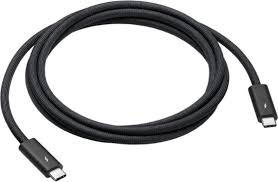
129
HDMI Cable
HDMI, or High-Definition Multimedia Interface, is a widely used interface for transmitting audio and video signals between devices. HDMI cables and ports are commonly found in various consumer electronics, providing a digital connection for high-definition content. HDMI supports high-definition video and audio, making it suitable for connecting devices such as HDTVs, monitors, Blu-ray players, gaming consoles, and audio-visual receivers.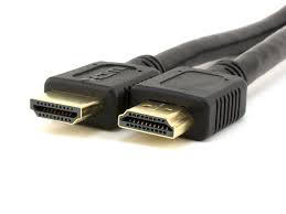
130
DisplayPort
DisplayPort is a digital display interface standard developed by the Video Electronics Standards Association (VESA). It is designed to provide a high-performance, digital connection for audio and video between computers and displays. DisplayPort is commonly used in desktop computers, laptops, monitors, and other devices. 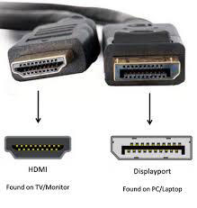
131
DVI Cable
DVI, or Digital Visual Interface, is a video display interface standard developed by the Digital Display Working Group (DDWG). It was designed to provide a high-quality digital connection between computers and displays, supporting both analog and digital signals. DVI is commonly used in desktop computers, monitors, projectors, and other display devices.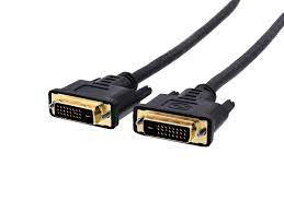
132
VGA Cable
VGA, or Video Graphics Array, is an analog video display interface standard that was introduced by IBM in 1987. VGA has been widely used for connecting computers and displays, especially in the earlier days of personal computing. While it has largely been superseded by digital interfaces like DVI, HDMI, and DisplayPort, VGA is still found on some older devices and is often used for compatibility with legacy equipment.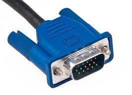
133
SATA Cable
Serial Advanced Technology Attachment (SATA) is a computer bus interface that connects host bus adapters to mass storage devices such as hard disk drives, optical drives, and solid-state drives. It is a popular standard for connecting internal storage devices in desktop computers, laptops, and servers.
SATA Revision 1.0
• SATA 1.5 Gbit/s, 1 meter
• SATA Revision 2.0
• SATA 3.0 Gbit/s, 1 meter
• SATA Revision 3.0
• SATA 6.0 Gbit/s, 1 meter
• SATA Revision 3.2
• SATA 16 Gbit/s, 1 meter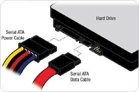
SATA Revision 1.0
• SATA 1.5 Gbit/s, 1 meter
• SATA Revision 2.0
• SATA 3.0 Gbit/s, 1 meter
• SATA Revision 3.0
• SATA 6.0 Gbit/s, 1 meter
• SATA Revision 3.2
• SATA 16 Gbit/s, 1 meter
134
SCSI Cable
SCSI stands for Small Computer System Interface. It is a set of standards for connecting and transferring data between computers and peripheral devices. SCSI is commonly used for connecting hard drives, CD-ROM drives, printers, scanners, and other devices to a computer. It's important to note that SCSI has become less common in consumer devices, with many modern computers and peripherals using other interfaces like SATA or USB. 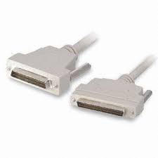
135
ESATA
eSATA, or External Serial ATA, is an external interface for connecting external storage devices, such as hard drives, to a computer. It is an extension of the SATA (Serial ATA) interface, which is commonly used for internal connections between storage devices and motherboards.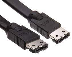
136
IDE
IDE, which stands for Integrated Drive Electronics, is a standard interface for connecting storage devices like hard drives and CD-ROM drives to a computer's motherboard. IDE has been largely replaced by newer and faster interfaces like SATA (Serial ATA) in modern computer systems. IDE cables typically have either 40 or 80 pins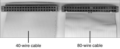
137
RJ-11 and RJ-45 are both types of connectors commonly used in networking and telecommunications, but they serve different purposes and have distinct characteristics:
RJ-11:
Usage: RJ-11 connectors are typically used for telephone lines and analog modems.
Number of Pins/Contacts: RJ-11 connectors usually have 6 positions and 2 or 4 conductors (6P2C or 6P4C), but they can sometimes be found with 4 positions and 2 conductors (4P2C).
Application: Commonly used in homes and offices for connecting telephones, fax machines, and dial-up modems.
RJ-45:
Usage: RJ-45 connectors are primarily used in Ethernet networking for both wired connections and in some cases, telephone systems that utilize Ethernet technology.
Number of Pins/Contacts: RJ-45 connectors have 8 positions and 8 conductors (8P8C).
Application: Widely used in networking applications for connecting computers, routers, switches, and other devices to local area networks (LANs). It is the standard connector for Ethernet cables.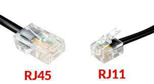
RJ11 and RJ45
RJ-11 and RJ-45 are both types of connectors commonly used in networking and telecommunications, but they serve different purposes and have distinct characteristics:
RJ-11:
Usage: RJ-11 connectors are typically used for telephone lines and analog modems.
Number of Pins/Contacts: RJ-11 connectors usually have 6 positions and 2 or 4 conductors (6P2C or 6P4C), but they can sometimes be found with 4 positions and 2 conductors (4P2C).
Application: Commonly used in homes and offices for connecting telephones, fax machines, and dial-up modems.
RJ-45:
Usage: RJ-45 connectors are primarily used in Ethernet networking for both wired connections and in some cases, telephone systems that utilize Ethernet technology.
Number of Pins/Contacts: RJ-45 connectors have 8 positions and 8 conductors (8P8C).
Application: Widely used in networking applications for connecting computers, routers, switches, and other devices to local area networks (LANs). It is the standard connector for Ethernet cables.
138
F Type Connector
The F-type connector is a type of coaxial connector commonly used in the transmission of audio and video signals, particularly in the context of cable television (CATV) and satellite television systems.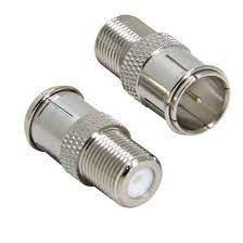
139
Molex
Molex is a company that specializes in the manufacturing of electronic connectors. The term "Molex" is often used as a genericized trademark to refer to various types of electrical connectors, especially those used in the computer and electronics industry. Molex connectors are widely used for internal and external connections in electronic devices, computers, and other applications. 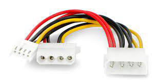
140
Lightening Cable and Port
A Lightning cable is a type of connector cable designed and manufactured by Apple Inc. It is used for charging and syncing Apple devices, including iPhones, iPads, and iPods. Lightning cables are used for both charging the device's battery and transferring data between the device and a computer. They are commonly used with Apple's power adapters or connected to USB ports for charging.
141
Virtual RAM
Virtual RAM, also known as virtual memory, is a memory management capability of an operating system (OS) that uses hardware and software to allow a computer to compensate for physical RAM (Random Access Memory) shortages by temporarily transferring data from RAM to disk storage.
Operating System Settings:
Virtual memory is managed by the operating system, and users typically don't need to install or configure it manually.
On Windows, the page file (virtual memory) settings can be adjusted in the System Properties. Go to "Control Panel" > "System" > "Advanced system settings" > "Advanced" tab > "Settings" under the "Performance" section > "Advanced" tab > "Change" under the "Virtual memory" section.
On Linux, virtual memory settings are managed by the kernel. Configuration files, such as /etc/fstab or kernel parameters, might be used to adjust swap space.
Automatic Management:
In most cases, modern operating systems automatically manage virtual memory settings based on the available physical RAM and system requirements.
The OS dynamically allocates space on the hard drive or SSD for virtual memory and adjusts it as needed.
Optimizing Performance:
If your computer is running slowly and you suspect virtual memory is a factor, you can optimize performance by upgrading physical RAM or managing background applications to reduce memory usage.
Avoid disabling the page file entirely, as this could lead to stability issues. Let the operating system manage virtual memory.
Check Available RAM:
To check your computer's RAM configuration, you can usually find information in the system properties or by using system monitoring tools.
Remember, virtual memory is a feature designed to provide additional resources when physical RAM is running low. While it can help prevent out-of-memory errors, heavy reliance on virtual memory may impact system performance. If you find your computer frequently using virtual memory, consider upgrading your physical RAM for improved performance.
Operating System Settings:
Virtual memory is managed by the operating system, and users typically don't need to install or configure it manually.
On Windows, the page file (virtual memory) settings can be adjusted in the System Properties. Go to "Control Panel" > "System" > "Advanced system settings" > "Advanced" tab > "Settings" under the "Performance" section > "Advanced" tab > "Change" under the "Virtual memory" section.
On Linux, virtual memory settings are managed by the kernel. Configuration files, such as /etc/fstab or kernel parameters, might be used to adjust swap space.
Automatic Management:
In most cases, modern operating systems automatically manage virtual memory settings based on the available physical RAM and system requirements.
The OS dynamically allocates space on the hard drive or SSD for virtual memory and adjusts it as needed.
Optimizing Performance:
If your computer is running slowly and you suspect virtual memory is a factor, you can optimize performance by upgrading physical RAM or managing background applications to reduce memory usage.
Avoid disabling the page file entirely, as this could lead to stability issues. Let the operating system manage virtual memory.
Check Available RAM:
To check your computer's RAM configuration, you can usually find information in the system properties or by using system monitoring tools.
Remember, virtual memory is a feature designed to provide additional resources when physical RAM is running low. While it can help prevent out-of-memory errors, heavy reliance on virtual memory may impact system performance. If you find your computer frequently using virtual memory, consider upgrading your physical RAM for improved performance.
142
RAM INSTALLS
Before you begin:
Compatibility:
Ensure that the RAM modules you have are compatible with your motherboard. Check the motherboard's manual or specifications for supported memory types, capacities, and speeds.
Matching Modules:
If you're adding RAM to existing modules, try to match the new RAM's specifications (speed, capacity, and latency) with the existing modules for optimal performance.
Power Off and Unplug:
Turn off your computer and unplug it from the power source. This is essential for safety and to prevent potential damage to the hardware.
Installation Steps:
Locate RAM Slots:
Identify the location of the RAM slots on your motherboard. Motherboards typically have multiple slots labeled DIMM (Dual Inline Memory Module).
Release Retaining Clips:
On both ends of each RAM slot, there are retaining clips. Push these clips outward to release any existing RAM modules.
Align Notches:
Check the notches on the RAM module. Align the notches on the module with those in the RAM slot. DDR3, DDR4, and DDR5 modules have different notch positions, ensuring proper orientation.
Insert at an Angle:
Hold the RAM module at about a 45-degree angle to the motherboard and gently insert it into the slot. Ensure that the module is fully seated.
Apply Even Pressure:
Apply even pressure on both ends of the RAM module until the retaining clips click into place on their own. You might hear a satisfying click when the RAM is securely installed.
Repeat for Additional Modules:
If you are installing multiple RAM modules, repeat the process for each one. Most motherboards have multiple RAM slots, and you may need to refer to your motherboard manual to determine the optimal configuration.
Close Retaining Clips:
Ensure that the retaining clips on both ends of the RAM slots are fully closed and holding the RAM modules securely.
Power On:
Plug in your computer and power it on. The system should automatically recognize the newly installed RAM.
Check System Information:
Verify the installed RAM through the operating system or system information tools. This can confirm that the system recognizes the new memory.
Notes:
Always refer to your motherboard's user manual for specific instructions related to RAM installation and compatibility.
Be aware of electrostatic discharge (ESD) and take precautions, such as grounding yourself, to avoid damaging sensitive components.
RAM modules are keyed, meaning they have notches that ensure proper orientation. Do not force the module if it doesn't fit easily.
If you encounter resistance, double-check the alignment and orientation of the RAM module.
Remember that DDR3, DDR4, and DDR5 are different generations of RAM with varying physical and electrical characteristics, so it's crucial to use the correct type for your motherboard.
ECC RAM (Error-Correcting Code RAM) is a type of computer memory that includes special error-checking and correcting circuitry on the RAM module. This technology is designed to detect and correct certain types of memory errors that may occur during data storage or retrieval. ECC RAM is commonly used in servers, workstations, and other systems where data integrity is critical.
Compatibility:
Ensure that the RAM modules you have are compatible with your motherboard. Check the motherboard's manual or specifications for supported memory types, capacities, and speeds.
Matching Modules:
If you're adding RAM to existing modules, try to match the new RAM's specifications (speed, capacity, and latency) with the existing modules for optimal performance.
Power Off and Unplug:
Turn off your computer and unplug it from the power source. This is essential for safety and to prevent potential damage to the hardware.
Installation Steps:
Locate RAM Slots:
Identify the location of the RAM slots on your motherboard. Motherboards typically have multiple slots labeled DIMM (Dual Inline Memory Module).
Release Retaining Clips:
On both ends of each RAM slot, there are retaining clips. Push these clips outward to release any existing RAM modules.
Align Notches:
Check the notches on the RAM module. Align the notches on the module with those in the RAM slot. DDR3, DDR4, and DDR5 modules have different notch positions, ensuring proper orientation.
Insert at an Angle:
Hold the RAM module at about a 45-degree angle to the motherboard and gently insert it into the slot. Ensure that the module is fully seated.
Apply Even Pressure:
Apply even pressure on both ends of the RAM module until the retaining clips click into place on their own. You might hear a satisfying click when the RAM is securely installed.
Repeat for Additional Modules:
If you are installing multiple RAM modules, repeat the process for each one. Most motherboards have multiple RAM slots, and you may need to refer to your motherboard manual to determine the optimal configuration.
Close Retaining Clips:
Ensure that the retaining clips on both ends of the RAM slots are fully closed and holding the RAM modules securely.
Power On:
Plug in your computer and power it on. The system should automatically recognize the newly installed RAM.
Check System Information:
Verify the installed RAM through the operating system or system information tools. This can confirm that the system recognizes the new memory.
Notes:
Always refer to your motherboard's user manual for specific instructions related to RAM installation and compatibility.
Be aware of electrostatic discharge (ESD) and take precautions, such as grounding yourself, to avoid damaging sensitive components.
RAM modules are keyed, meaning they have notches that ensure proper orientation. Do not force the module if it doesn't fit easily.
If you encounter resistance, double-check the alignment and orientation of the RAM module.
Remember that DDR3, DDR4, and DDR5 are different generations of RAM with varying physical and electrical characteristics, so it's crucial to use the correct type for your motherboard.
ECC RAM (Error-Correcting Code RAM) is a type of computer memory that includes special error-checking and correcting circuitry on the RAM module. This technology is designed to detect and correct certain types of memory errors that may occur during data storage or retrieval. ECC RAM is commonly used in servers, workstations, and other systems where data integrity is critical.
143
Installing SODIMM
Before you begin:
Compatibility:
Make sure the SO-DIMM RAM module you have is compatible with your laptop or computer. Check the specifications for supported memory types, capacities, and speeds.
Power Off:
Turn off your laptop or computer and disconnect the power source. This is crucial for safety and to avoid potential damage to the hardware.
Installation Steps:
Locate the RAM Slots:
Identify the location of the RAM slots on your laptop. This information can often be found in the user manual or on the manufacturer's website.
Remove Battery (if applicable):
If your laptop has a removable battery, it's a good practice to remove it before making any hardware changes.
Ground Yourself:
Touch a metal surface or use an antistatic wrist strap to discharge any static electricity and prevent damage to the RAM module.
Access the RAM Compartment:
In many laptops, the RAM compartment is accessible through a panel on the bottom. Use a screwdriver to remove the screws securing the panel.
Identify the RAM Slots:
Look for the existing RAM modules and identify the available slots. Some laptops may have both accessible slots and soldered RAM.
Release Retaining Clips:
On each side of the existing RAM module(s), there are small retaining clips. Gently push these clips outward to release the existing RAM module.
Align and Insert the SO-DIMM:
Align the notches on the SO-DIMM module with those on the slot. Insert the module into the slot at about a 45-degree angle, and then gently press it down until the clips on both sides click into place.
Secure the Module:
Once the SO-DIMM is seated properly, the retaining clips should automatically secure it in place. Ensure that the module is firmly in position.
Close the Panel:
If you opened a panel to access the RAM compartment, secure it back in place using the screws.
Replace Battery (if removed):
If you removed the battery, reinsert it and secure it in place.
Power On:
Power on your laptop or computer. The system should recognize the new RAM, and you can verify the installed memory through the operating system or system information.
Notes:
Always refer to your laptop's user manual for specific instructions related to RAM upgrades.
Be aware of warranty implications, as opening certain laptops may void the warranty.
Ensure that the SO-DIMM module is compatible with your system's specifications.
If you are unsure or uncomfortable with the process, consider seeking assistance from a professional or the laptop's manufacturer.
Compatibility:
Make sure the SO-DIMM RAM module you have is compatible with your laptop or computer. Check the specifications for supported memory types, capacities, and speeds.
Power Off:
Turn off your laptop or computer and disconnect the power source. This is crucial for safety and to avoid potential damage to the hardware.
Installation Steps:
Locate the RAM Slots:
Identify the location of the RAM slots on your laptop. This information can often be found in the user manual or on the manufacturer's website.
Remove Battery (if applicable):
If your laptop has a removable battery, it's a good practice to remove it before making any hardware changes.
Ground Yourself:
Touch a metal surface or use an antistatic wrist strap to discharge any static electricity and prevent damage to the RAM module.
Access the RAM Compartment:
In many laptops, the RAM compartment is accessible through a panel on the bottom. Use a screwdriver to remove the screws securing the panel.
Identify the RAM Slots:
Look for the existing RAM modules and identify the available slots. Some laptops may have both accessible slots and soldered RAM.
Release Retaining Clips:
On each side of the existing RAM module(s), there are small retaining clips. Gently push these clips outward to release the existing RAM module.
Align and Insert the SO-DIMM:
Align the notches on the SO-DIMM module with those on the slot. Insert the module into the slot at about a 45-degree angle, and then gently press it down until the clips on both sides click into place.
Secure the Module:
Once the SO-DIMM is seated properly, the retaining clips should automatically secure it in place. Ensure that the module is firmly in position.
Close the Panel:
If you opened a panel to access the RAM compartment, secure it back in place using the screws.
Replace Battery (if removed):
If you removed the battery, reinsert it and secure it in place.
Power On:
Power on your laptop or computer. The system should recognize the new RAM, and you can verify the installed memory through the operating system or system information.
Notes:
Always refer to your laptop's user manual for specific instructions related to RAM upgrades.
Be aware of warranty implications, as opening certain laptops may void the warranty.
Ensure that the SO-DIMM module is compatible with your system's specifications.
If you are unsure or uncomfortable with the process, consider seeking assistance from a professional or the laptop's manufacturer.
144
Installing Channel RAM
Before you begin:
Compatibility:
Ensure that the RAM modules you have are compatible with your motherboard. Check the motherboard's manual or specifications for supported memory types, capacities, and speeds.
Matching Specifications:
If you're adding RAM to existing modules, try to match the new RAM's specifications (speed, capacity, and latency) with the existing modules for optimal performance.
Power Off and Unplug:
Turn off your computer and unplug it from the power source. This is essential for safety and to prevent potential damage to the hardware.
Installation Steps:
Locate RAM Slots:
Identify the RAM slots on your motherboard. For dual-channel configurations, there are usually two sets of slots, often color-coded (e.g., black and blue).
Release Retaining Clips:
On both ends of the RAM slots, there are retaining clips. Push these clips outward to release any existing RAM modules.
Check Channel Configuration:
Refer to your motherboard manual to determine the correct configuration for dual-channel memory. Typically, you'll want to install RAM modules in slots that belong to the same channel (e.g., both in the black slots or both in the blue slots).
Align Notches:
Check the notches on the RAM modules. Align the notches on each module with those in the corresponding RAM slots.
Insert at an Angle:
Hold each RAM module at about a 45-degree angle to the motherboard and gently insert them into the designated slots.
Apply Even Pressure:
Apply even pressure on both ends of each RAM module until the retaining clips click into place on their own. You might hear a satisfying click when the RAM is securely installed.
Close Retaining Clips:
Ensure that the retaining clips on both ends of the RAM slots are fully closed and holding the RAM modules securely.
Power On:
Plug in your computer and power it on. The system should automatically recognize the newly installed dual-channel RAM.
Check System Information:
Verify the installed RAM through the operating system or system information tools. This can confirm that the system recognizes the new memory.
Notes:
Always refer to your motherboard's user manual for specific instructions related to RAM installation and compatibility.
Be aware of electrostatic discharge (ESD) and take precautions, such as grounding yourself, to avoid damaging sensitive components.
Dual-channel RAM configurations can provide increased memory bandwidth and improved performance compared to single-channel configurations. If your motherboard supports dual-channel and you have matching RAM modules, it's generally recommended to install them in the correct slots to take advantage of the dual-channel capability.
Compatibility:
Ensure that the RAM modules you have are compatible with your motherboard. Check the motherboard's manual or specifications for supported memory types, capacities, and speeds.
Matching Specifications:
If you're adding RAM to existing modules, try to match the new RAM's specifications (speed, capacity, and latency) with the existing modules for optimal performance.
Power Off and Unplug:
Turn off your computer and unplug it from the power source. This is essential for safety and to prevent potential damage to the hardware.
Installation Steps:
Locate RAM Slots:
Identify the RAM slots on your motherboard. For dual-channel configurations, there are usually two sets of slots, often color-coded (e.g., black and blue).
Release Retaining Clips:
On both ends of the RAM slots, there are retaining clips. Push these clips outward to release any existing RAM modules.
Check Channel Configuration:
Refer to your motherboard manual to determine the correct configuration for dual-channel memory. Typically, you'll want to install RAM modules in slots that belong to the same channel (e.g., both in the black slots or both in the blue slots).
Align Notches:
Check the notches on the RAM modules. Align the notches on each module with those in the corresponding RAM slots.
Insert at an Angle:
Hold each RAM module at about a 45-degree angle to the motherboard and gently insert them into the designated slots.
Apply Even Pressure:
Apply even pressure on both ends of each RAM module until the retaining clips click into place on their own. You might hear a satisfying click when the RAM is securely installed.
Close Retaining Clips:
Ensure that the retaining clips on both ends of the RAM slots are fully closed and holding the RAM modules securely.
Power On:
Plug in your computer and power it on. The system should automatically recognize the newly installed dual-channel RAM.
Check System Information:
Verify the installed RAM through the operating system or system information tools. This can confirm that the system recognizes the new memory.
Notes:
Always refer to your motherboard's user manual for specific instructions related to RAM installation and compatibility.
Be aware of electrostatic discharge (ESD) and take precautions, such as grounding yourself, to avoid damaging sensitive components.
Dual-channel RAM configurations can provide increased memory bandwidth and improved performance compared to single-channel configurations. If your motherboard supports dual-channel and you have matching RAM modules, it's generally recommended to install them in the correct slots to take advantage of the dual-channel capability.
145
HARD DRIVE SPEEDS
Rotational
Speed
(rpm) -
Average
Rotational
Latency
15,000 - 2 ms
10,000 - 3 ms
7,200 - 4.16 ms
5,400 - 5.55 ms
HDD Speeds:
5400 RPM HDDs: Typically found in budget laptops and storage-focused applications.
7200 RPM HDDs: Offer better performance and are commonly used in gaming laptops and desktops.
SATA SSD Speeds:
SATA SSDs: Sequential read/write speeds can range from 500 MB/s to 600 MB/s and beyond.
NVMe SSD Speeds:
NVMe SSDs: Can achieve much higher speeds, with sequential read/write speeds commonly exceeding 1000 MB/s and reaching several gigabytes per second.
When selecting a hard drive, consider your specific use case. For operating system and application installations, an SSD with higher data transfer rates is generally recommended for improved overall system responsiveness. HDDs may still be suitable for mass storage or budget-oriented applications. Many users opt for a combination of SSD for the operating system and essential applications, and HDD for bulk storage.
Speed
(rpm) -
Average
Rotational
Latency
15,000 - 2 ms
10,000 - 3 ms
7,200 - 4.16 ms
5,400 - 5.55 ms
HDD Speeds:
5400 RPM HDDs: Typically found in budget laptops and storage-focused applications.
7200 RPM HDDs: Offer better performance and are commonly used in gaming laptops and desktops.
SATA SSD Speeds:
SATA SSDs: Sequential read/write speeds can range from 500 MB/s to 600 MB/s and beyond.
NVMe SSD Speeds:
NVMe SSDs: Can achieve much higher speeds, with sequential read/write speeds commonly exceeding 1000 MB/s and reaching several gigabytes per second.
When selecting a hard drive, consider your specific use case. For operating system and application installations, an SSD with higher data transfer rates is generally recommended for improved overall system responsiveness. HDDs may still be suitable for mass storage or budget-oriented applications. Many users opt for a combination of SSD for the operating system and essential applications, and HDD for bulk storage.
146
Hard Drive Form Factors
******3.5-Inch Form Factor:
Usage: Traditional desktop hard drives are typically 3.5 inches in width.
Mounting: They are designed for installation in desktop computers.
Connectivity: Usually connected through SATA (Serial ATA) interfaces.
Capacity: Available in a wide range of capacities, including high-capacity drives for mass storage.
****** 2.5-Inch Form Factor:
Usage: Commonly used in laptops, external drives, and some small form factor desktops.
Mounting: Smaller and more compact than 3.5-inch drives, making them suitable for portable devices.
Connectivity: Typically connected through SATA for internal drives, and USB or other interfaces for external drives.
Capacity: Available in various capacities, and widely used in SSDs (Solid State Drives) as well.
3. 1.8-Inch Form Factor:
Usage: Primarily found in ultraportable laptops and some portable media players.
Mounting: Smaller than 2.5-inch drives, making them suitable for slim and lightweight devices.
Connectivity: Often uses specialized connectors and interfaces, including micro SATA and ZIF (Zero Insertion Force).
Capacity: Generally lower capacity compared to larger form factors.
4. 5.25-Inch Form Factor:
Usage: Historically used for optical drives like CD/DVD drives. Not commonly used for hard drives.
Mounting: Larger size, designed to fit into 5.25-inch drive bays in desktop cases.
Connectivity: Typically uses SATA or IDE (Integrated Drive Electronics) interfaces.
Capacity: Historically used for optical drives with lower data storage capacities.
5. M.2 Form Factor:
Usage: Common in modern laptops, ultrabooks, and desktops for both SSDs and certain types of Wi-Fi and Bluetooth modules.
Mounting: Smaller and more compact, designed for space-efficient installations.
Connectivity: Utilizes the M.2 slot on the motherboard, supporting interfaces like SATA, PCIe, and NVMe for high-speed data transfer.
Capacity: Often used for high-performance SSDs with various capacities.
6. U.2 Form Factor:
Usage: Primarily used for enterprise-class SSDs but less common in consumer devices.
Mounting: Larger than M.2, designed for servers and high-performance storage solutions.
Connectivity: Uses the U.2 connector and supports high-speed interfaces like PCIe and NVMe.
Capacity: Used for high-capacity and high-performance SSDs in enterprise environments.
Usage: Traditional desktop hard drives are typically 3.5 inches in width.
Mounting: They are designed for installation in desktop computers.
Connectivity: Usually connected through SATA (Serial ATA) interfaces.
Capacity: Available in a wide range of capacities, including high-capacity drives for mass storage.
****** 2.5-Inch Form Factor:
Usage: Commonly used in laptops, external drives, and some small form factor desktops.
Mounting: Smaller and more compact than 3.5-inch drives, making them suitable for portable devices.
Connectivity: Typically connected through SATA for internal drives, and USB or other interfaces for external drives.
Capacity: Available in various capacities, and widely used in SSDs (Solid State Drives) as well.
3. 1.8-Inch Form Factor:
Usage: Primarily found in ultraportable laptops and some portable media players.
Mounting: Smaller than 2.5-inch drives, making them suitable for slim and lightweight devices.
Connectivity: Often uses specialized connectors and interfaces, including micro SATA and ZIF (Zero Insertion Force).
Capacity: Generally lower capacity compared to larger form factors.
4. 5.25-Inch Form Factor:
Usage: Historically used for optical drives like CD/DVD drives. Not commonly used for hard drives.
Mounting: Larger size, designed to fit into 5.25-inch drive bays in desktop cases.
Connectivity: Typically uses SATA or IDE (Integrated Drive Electronics) interfaces.
Capacity: Historically used for optical drives with lower data storage capacities.
5. M.2 Form Factor:
Usage: Common in modern laptops, ultrabooks, and desktops for both SSDs and certain types of Wi-Fi and Bluetooth modules.
Mounting: Smaller and more compact, designed for space-efficient installations.
Connectivity: Utilizes the M.2 slot on the motherboard, supporting interfaces like SATA, PCIe, and NVMe for high-speed data transfer.
Capacity: Often used for high-performance SSDs with various capacities.
6. U.2 Form Factor:
Usage: Primarily used for enterprise-class SSDs but less common in consumer devices.
Mounting: Larger than M.2, designed for servers and high-performance storage solutions.
Connectivity: Uses the U.2 connector and supports high-speed interfaces like PCIe and NVMe.
Capacity: Used for high-capacity and high-performance SSDs in enterprise environments.
147
SSD & Types
An SSD, or Solid State Drive, is a type of data storage device that uses NAND-based flash memory to store data persistently. SSDs have become increasingly popular due to their speed, reliability, and energy efficiency compared to traditional Hard Disk Drives (HDDs). Here are some key features and information about
SSDs Key Features:
No Moving Parts:
Unlike HDDs, SSDs have no moving parts. Data is stored in memory chips, allowing for faster data access times and durability.
Speed:
SSDs offer significantly faster read and write speeds compared to HDDs. This results in quicker boot times, faster application loading, and improved overall system responsiveness.
Durability:
Because there are no mechanical components, SSDs are more durable and less susceptible to physical shock or vibration. This makes them ideal for use in laptops and portable devices.
Energy Efficiency:
SSDs consume less power than traditional HDDs. This can lead to longer battery life in laptops and reduced power consumption in desktop systems.
Silent Operation:
With no moving parts, SSDs operate silently, contributing to a quieter computing environment.
Compact Form Factors:
SSDs come in various form factors, including 2.5-inch drives for laptops, M.2 drives for ultrabooks and compact systems, and PCIe-based drives for high-performance
applications.
Random Access:
SSDs excel at random access, meaning they can quickly access and retrieve data from various locations on the drive. This is particularly beneficial for tasks involving multiple small files.
Types of SSDs:
SATA SSDs:
Connected via the SATA interface, these SSDs are a common and affordable option. They provide a significant speed improvement over HDDs.
NVMe SSDs:
Utilize the NVMe (Non-Volatile Memory Express) protocol and connect directly to the PCIe (Peripheral Component Interconnect Express) interface. NVMe SSDs offer even higher speeds than SATA SSDs.
M.2 SSDs:
A compact form factor that connects directly to the motherboard through the M.2 slot. M.2 SSDs can use SATA or NVMe interfaces.
External SSDs:
Designed to connect externally via USB or Thunderbolt, providing a portable and fast storage solution.
Considerations when Choosing an SSD:
Capacity:
SSDs are available in various capacities. Choose a capacity that meets your storage needs.
Usage Scenario:
Consider the intended use, whether it's for an operating system drive, gaming, content creation, or general storage.
Endurance:
SSDs have a limited number of write cycles. Higher-end SSDs often have higher endurance, making them suitable for tasks with heavy write operations.
Brand and Reliability:
Choose reputable brands known for producing reliable SSDs. Read reviews and consider warranty and support options.
Price:
SSD prices have become more competitive, but they are generally more expensive than HDDs. Consider the performance benefits when evaluating the cost.
SSDs have become the standard for primary storage in modern computing devices due to their performance advantages. When upgrading or building a new system, an SSD is often recommended for faster and more responsive storage.
SSDs Key Features:
No Moving Parts:
Unlike HDDs, SSDs have no moving parts. Data is stored in memory chips, allowing for faster data access times and durability.
Speed:
SSDs offer significantly faster read and write speeds compared to HDDs. This results in quicker boot times, faster application loading, and improved overall system responsiveness.
Durability:
Because there are no mechanical components, SSDs are more durable and less susceptible to physical shock or vibration. This makes them ideal for use in laptops and portable devices.
Energy Efficiency:
SSDs consume less power than traditional HDDs. This can lead to longer battery life in laptops and reduced power consumption in desktop systems.
Silent Operation:
With no moving parts, SSDs operate silently, contributing to a quieter computing environment.
Compact Form Factors:
SSDs come in various form factors, including 2.5-inch drives for laptops, M.2 drives for ultrabooks and compact systems, and PCIe-based drives for high-performance
applications.
Random Access:
SSDs excel at random access, meaning they can quickly access and retrieve data from various locations on the drive. This is particularly beneficial for tasks involving multiple small files.
Types of SSDs:
SATA SSDs:
Connected via the SATA interface, these SSDs are a common and affordable option. They provide a significant speed improvement over HDDs.
NVMe SSDs:
Utilize the NVMe (Non-Volatile Memory Express) protocol and connect directly to the PCIe (Peripheral Component Interconnect Express) interface. NVMe SSDs offer even higher speeds than SATA SSDs.
M.2 SSDs:
A compact form factor that connects directly to the motherboard through the M.2 slot. M.2 SSDs can use SATA or NVMe interfaces.
External SSDs:
Designed to connect externally via USB or Thunderbolt, providing a portable and fast storage solution.
Considerations when Choosing an SSD:
Capacity:
SSDs are available in various capacities. Choose a capacity that meets your storage needs.
Usage Scenario:
Consider the intended use, whether it's for an operating system drive, gaming, content creation, or general storage.
Endurance:
SSDs have a limited number of write cycles. Higher-end SSDs often have higher endurance, making them suitable for tasks with heavy write operations.
Brand and Reliability:
Choose reputable brands known for producing reliable SSDs. Read reviews and consider warranty and support options.
Price:
SSD prices have become more competitive, but they are generally more expensive than HDDs. Consider the performance benefits when evaluating the cost.
SSDs have become the standard for primary storage in modern computing devices due to their performance advantages. When upgrading or building a new system, an SSD is often recommended for faster and more responsive storage.
148
PCIe
PCIe, which stands for Peripheral Component Interconnect Express, is a high-speed serial computer expansion bus standard. It is commonly used for connecting various hardware devices, including graphics cards, storage devices, network cards, and other peripherals, to a motherboard. PCIe offers significant improvements over its predecessor, PCI (Peripheral Component Interconnect), providing faster data transfer rates and increased bandwidth. Here are key features and information about PCIe:
Key Features:
High-Speed Serial Interface:
PCIe is a serial interface, allowing for high-speed data transfer between the motherboard and connected devices.
Increased Bandwidth:
PCIe provides significantly higher bandwidth compared to PCI, allowing for faster communication between the CPU and connected components.
Scalability:
PCIe is scalable, meaning it supports multiple lanes (also referred to as "lanes" or "links"). A single PCIe lane consists of two differential signaling pairs (one for transmit and one for receive).
Multiple Versions:
PCIe has gone through several generations, each offering increased data transfer rates. Common versions include PCIe 1.0, 2.0, 3.0, 4.0, and 5.0.
Backward Compatibility:
PCIe is backward compatible, meaning devices designed for earlier versions can generally work in newer PCIe slots, though they might operate at lower speeds.
Hot Swapping:
PCIe supports hot swapping, allowing users to add or remove PCIe devices without powering down the system.
PCIe Generations and Data Transfer Rates:
PCIe 1.0:
Introduced in 2003 with a maximum data transfer rate of 2.5 GT/s (gigatransfers per second) per lane.
PCIe 2.0:
Introduced in 2007, doubling the data transfer rate to 5 GT/s per lane.
PCIe 3.0:
Introduced in 2010, further doubling the data transfer rate to 8 GT/s per lane.
PCIe 4.0:
Introduced in 2017, doubling the data transfer rate again to 16 GT/s per lane.
PCIe 5.0:
Introduced in 2019, providing a data transfer rate of 32 GT/s per lane.
Common PCIe Devices:
Graphics Cards (GPUs):
PCIe is widely used for connecting dedicated graphics cards to the motherboard. Modern GPUs often use PCIe x16 slots.
Storage Devices:
NVMe SSDs and other high-speed storage devices commonly use PCIe interfaces for faster data transfer rates.
Network Cards:
High-performance network cards, especially those used in servers and data centers, often utilize PCIe for increased bandwidth.
Expansion Cards:
Various expansion cards, such as audio cards, USB controllers, and more, can use PCIe slots on the motherboard.
Thunderbolt:
Thunderbolt, a high-speed data transfer and display interface, often uses a PCIe connection.
PCIe plays a crucial role in modern computing, facilitating high-speed communication between the CPU and various peripherals. When building or upgrading a computer, understanding PCIe specifications is important to ensure compatibility and take advantage of the latest technologies.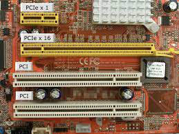
Key Features:
High-Speed Serial Interface:
PCIe is a serial interface, allowing for high-speed data transfer between the motherboard and connected devices.
Increased Bandwidth:
PCIe provides significantly higher bandwidth compared to PCI, allowing for faster communication between the CPU and connected components.
Scalability:
PCIe is scalable, meaning it supports multiple lanes (also referred to as "lanes" or "links"). A single PCIe lane consists of two differential signaling pairs (one for transmit and one for receive).
Multiple Versions:
PCIe has gone through several generations, each offering increased data transfer rates. Common versions include PCIe 1.0, 2.0, 3.0, 4.0, and 5.0.
Backward Compatibility:
PCIe is backward compatible, meaning devices designed for earlier versions can generally work in newer PCIe slots, though they might operate at lower speeds.
Hot Swapping:
PCIe supports hot swapping, allowing users to add or remove PCIe devices without powering down the system.
PCIe Generations and Data Transfer Rates:
PCIe 1.0:
Introduced in 2003 with a maximum data transfer rate of 2.5 GT/s (gigatransfers per second) per lane.
PCIe 2.0:
Introduced in 2007, doubling the data transfer rate to 5 GT/s per lane.
PCIe 3.0:
Introduced in 2010, further doubling the data transfer rate to 8 GT/s per lane.
PCIe 4.0:
Introduced in 2017, doubling the data transfer rate again to 16 GT/s per lane.
PCIe 5.0:
Introduced in 2019, providing a data transfer rate of 32 GT/s per lane.
Common PCIe Devices:
Graphics Cards (GPUs):
PCIe is widely used for connecting dedicated graphics cards to the motherboard. Modern GPUs often use PCIe x16 slots.
Storage Devices:
NVMe SSDs and other high-speed storage devices commonly use PCIe interfaces for faster data transfer rates.
Network Cards:
High-performance network cards, especially those used in servers and data centers, often utilize PCIe for increased bandwidth.
Expansion Cards:
Various expansion cards, such as audio cards, USB controllers, and more, can use PCIe slots on the motherboard.
Thunderbolt:
Thunderbolt, a high-speed data transfer and display interface, often uses a PCIe connection.
PCIe plays a crucial role in modern computing, facilitating high-speed communication between the CPU and various peripherals. When building or upgrading a computer, understanding PCIe specifications is important to ensure compatibility and take advantage of the latest technologies.
149
mSATA Form Factor
mSATA, which stands for mini-SATA, is a small form factor for solid-state drives (SSDs) that was designed to be a compact and space-saving storage solution. The mSATA form factor was commonly used in ultrabooks, netbooks, and other small form factor devices. However, it has become less common in recent years as newer form factors, such as M.2, have gained popularity. Here are some key features and information about the mSATA form factor:
Key Features:
Size:
The mSATA form factor is small, measuring approximately 50.8mm in length, 29.85mm in width, and 3.75mm in height.
Connector:
mSATA drives use a Mini PCIe connector, which is a smaller version of the standard PCIe connector. The Mini PCIe connector provides both data and power connections.
Compatibility:
mSATA was designed to be compatible with the existing PCIe Mini Card slot, which was commonly used for wireless network cards in laptops and other portable devices. However, it's important to note that mSATA and PCIe Mini Card are not interchangeable.
Storage Capacity:
mSATA SSDs are available in various storage capacities, similar to other SSD form factors. They can range from small capacities for basic storage needs to larger capacities suitable for operating systems and applications.
Usage:
mSATA SSDs were often used in ultrabooks, netbooks, and other compact devices where space is limited. They provided a faster and more reliable storage solution compared to traditional hard disk drives (HDDs).
Limitations and Evolution:
Superseded by M.2:
While mSATA was popular for a period, it has been largely superseded by the M.2 form factor, which offers additional advantages such as higher data transfer rates and support for more advanced technologies like NVMe (Non-Volatile Memory Express).
Availability:
The availability of new devices featuring mSATA slots has decreased, as M.2 has become the more prevalent and versatile choice for compact storage solutions.
Transition to M.2:
Many modern laptops and ultrabooks have transitioned to using M.2 slots for SSDs, offering faster data transfer rates and supporting a wider range of storage technologies.
While mSATA is less common in contemporary devices, it was an important form factor during the transition from traditional HDDs to SSDs in compact and portable computing devices. If you have a device with an mSATA slot, it's essential to ensure compatibility when considering storage upgrades, as newer laptops and devices may use M.2 or other form factors instead.
Key Features:
Size:
The mSATA form factor is small, measuring approximately 50.8mm in length, 29.85mm in width, and 3.75mm in height.
Connector:
mSATA drives use a Mini PCIe connector, which is a smaller version of the standard PCIe connector. The Mini PCIe connector provides both data and power connections.
Compatibility:
mSATA was designed to be compatible with the existing PCIe Mini Card slot, which was commonly used for wireless network cards in laptops and other portable devices. However, it's important to note that mSATA and PCIe Mini Card are not interchangeable.
Storage Capacity:
mSATA SSDs are available in various storage capacities, similar to other SSD form factors. They can range from small capacities for basic storage needs to larger capacities suitable for operating systems and applications.
Usage:
mSATA SSDs were often used in ultrabooks, netbooks, and other compact devices where space is limited. They provided a faster and more reliable storage solution compared to traditional hard disk drives (HDDs).
Limitations and Evolution:
Superseded by M.2:
While mSATA was popular for a period, it has been largely superseded by the M.2 form factor, which offers additional advantages such as higher data transfer rates and support for more advanced technologies like NVMe (Non-Volatile Memory Express).
Availability:
The availability of new devices featuring mSATA slots has decreased, as M.2 has become the more prevalent and versatile choice for compact storage solutions.
Transition to M.2:
Many modern laptops and ultrabooks have transitioned to using M.2 slots for SSDs, offering faster data transfer rates and supporting a wider range of storage technologies.
While mSATA is less common in contemporary devices, it was an important form factor during the transition from traditional HDDs to SSDs in compact and portable computing devices. If you have a device with an mSATA slot, it's essential to ensure compatibility when considering storage upgrades, as newer laptops and devices may use M.2 or other form factors instead.
150
RAID
RAID (Redundant Array of Independent Disks) configurations are methods of combining multiple physical drives into a single logical storage unit. Each RAID configuration offers different levels of performance, redundancy, and capacity. Here are some common RAID configurations:
1. RAID 0 (Striping):
Description:
RAID 0 involves striping data across multiple drives without any parity or mirroring.
Performance:
Provides increased performance by distributing data across multiple drives. Read and write operations can be faster.
Capacity:
Offers the full sum of the capacities of all drives in the array.
Redundancy:
No redundancy; if one drive fails, all data is lost.
Use Case:
Suitable for situations where performance is a priority, and data redundancy is not critical, such as video editing or temporary storage.
2. RAID 1 (Mirroring):
Description:
RAID 1 involves mirroring data across two drives, providing redundancy.
Performance:
Read performance can be enhanced, but write performance may be similar to that of a single drive.
Capacity:
Offers the capacity of a single drive since data is mirrored.
Redundancy:
Provides redundancy; if one drive fails, data is still available on the mirrored drive.
Use Case:
Used for critical applications where data integrity and redundancy are priorities, at the expense of overall storage capacity.
3. RAID 5 (Striping with Distributed Parity):
Description:
RAID 5 involves striping data across multiple drives with distributed parity for fault tolerance.
Performance:
Balanced performance with both read and write operations benefiting from striping.
Capacity:
Offers the capacity of all drives in the array except for one drive used for parity.
Redundancy:
Provides fault tolerance; if one drive fails, data can be reconstructed using parity information.
Use Case:
Commonly used in environments where a balance of performance and redundancy is required, such as file servers.
4. RAID 10 (Mirrored Striping):
Description:
RAID 10 combines mirroring (RAID 1) and striping (RAID 0) for both redundancy and performance.
Performance:
Excellent performance with both read and write operations benefiting from striping.
Capacity:
Offers the capacity of half the drives in the array due to mirroring.
Redundancy:
Provides high redundancy; can tolerate the failure of one or more drives, depending on the specific configuration.
Use Case:
Suitable for applications requiring high performance and high data redundancy, such as database servers.
Considerations:
Data Security:
RAID configurations provide varying levels of data security. RAID 1, 5, and 10 offer redundancy, while RAID 0 does not provide any fault tolerance.
Performance vs. Redundancy:
Choose a RAID configuration based on the balance between performance and redundancy required for your specific use case.
Drive Size and Speed:
It's advisable to use drives of the same size and speed within a RAID array to optimize performance and capacity.
Rebuilding Time:
Consider the time it takes to rebuild a RAID array in case of a drive failure, especially for larger arrays.
When setting up a RAID array, it's essential to understand the specific requirements of your applications and choose a configuration that aligns with your priorities for performance, capacity, and data redundancy. Additionally, regular backups are crucial regardless of RAID configuration to protect against data loss from various types of failures.
1. RAID 0 (Striping):
Description:
RAID 0 involves striping data across multiple drives without any parity or mirroring.
Performance:
Provides increased performance by distributing data across multiple drives. Read and write operations can be faster.
Capacity:
Offers the full sum of the capacities of all drives in the array.
Redundancy:
No redundancy; if one drive fails, all data is lost.
Use Case:
Suitable for situations where performance is a priority, and data redundancy is not critical, such as video editing or temporary storage.
2. RAID 1 (Mirroring):
Description:
RAID 1 involves mirroring data across two drives, providing redundancy.
Performance:
Read performance can be enhanced, but write performance may be similar to that of a single drive.
Capacity:
Offers the capacity of a single drive since data is mirrored.
Redundancy:
Provides redundancy; if one drive fails, data is still available on the mirrored drive.
Use Case:
Used for critical applications where data integrity and redundancy are priorities, at the expense of overall storage capacity.
3. RAID 5 (Striping with Distributed Parity):
Description:
RAID 5 involves striping data across multiple drives with distributed parity for fault tolerance.
Performance:
Balanced performance with both read and write operations benefiting from striping.
Capacity:
Offers the capacity of all drives in the array except for one drive used for parity.
Redundancy:
Provides fault tolerance; if one drive fails, data can be reconstructed using parity information.
Use Case:
Commonly used in environments where a balance of performance and redundancy is required, such as file servers.
4. RAID 10 (Mirrored Striping):
Description:
RAID 10 combines mirroring (RAID 1) and striping (RAID 0) for both redundancy and performance.
Performance:
Excellent performance with both read and write operations benefiting from striping.
Capacity:
Offers the capacity of half the drives in the array due to mirroring.
Redundancy:
Provides high redundancy; can tolerate the failure of one or more drives, depending on the specific configuration.
Use Case:
Suitable for applications requiring high performance and high data redundancy, such as database servers.
Considerations:
Data Security:
RAID configurations provide varying levels of data security. RAID 1, 5, and 10 offer redundancy, while RAID 0 does not provide any fault tolerance.
Performance vs. Redundancy:
Choose a RAID configuration based on the balance between performance and redundancy required for your specific use case.
Drive Size and Speed:
It's advisable to use drives of the same size and speed within a RAID array to optimize performance and capacity.
Rebuilding Time:
Consider the time it takes to rebuild a RAID array in case of a drive failure, especially for larger arrays.
When setting up a RAID array, it's essential to understand the specific requirements of your applications and choose a configuration that aligns with your priorities for performance, capacity, and data redundancy. Additionally, regular backups are crucial regardless of RAID configuration to protect against data loss from various types of failures.
151
Removable Storage
Flash Drives (USB Flash Drives):
Description:
Flash drives, also known as USB flash drives or thumb drives, are portable storage devices that use flash memory to store data.
Connection:
Typically connect to computers and other devices through a USB (Universal Serial Bus) port.
Capacity:
Available in various capacities, ranging from a few gigabytes to several terabytes for newer high-capacity models.
Use Case:
Commonly used for portable data storage, file transfer, and as a bootable device for operating system installations.
2. Memory Cards:
Description:
Memory cards are small, removable storage devices commonly used in cameras, smartphones, and other portable devices.
Types:
Various formats, including SD (Secure Digital), microSD, CompactFlash, and others, each designed for specific devices.
Capacity:
Available in a range of capacities, and higher-capacity cards are often used for storing large files like photos and videos.
Use Case:
Widely used in digital cameras, smartphones, tablets, and other devices to expand storage capacity.
3. Optical Drives:
Description:
Optical drives use laser technology to read and write data on optical discs, such as CDs, DVDs, and Blu-ray discs.
Types:
CD-ROM, DVD-ROM, DVD-RW, Blu-ray, etc.
Connection:
Connect to computers through interfaces like SATA (Serial ATA) or, in older systems, IDE (Integrated Drive Electronics).
Use Case:
Used for reading and writing data on optical discs, installing software, playing movies, and creating backup discs.
Considerations:
Portability:
Flash drives and memory cards are highly portable, making them convenient for on-the-go use.
Durability:
Flash drives and memory cards are solid-state devices, making them more durable and resistant to physical shocks compared to optical discs.
Read/Write Speed:
Flash drives and memory cards generally offer faster read and write speeds compared to optical drives.
Media Longevity:
Optical discs can degrade over time, while flash drives and memory cards have a longer lifespan.
Capacity and Cost:
Flash drives and memory cards come in a wide range of capacities and price points, allowing users to choose based on their storage needs and budget.
Compatibility:
Ensure compatibility with devices when choosing memory cards or flash drives, especially regarding formats and storage capacity.
The choice between these storage devices depends on factors such as portability, capacity requirements, read/write speed, and the specific use case. For example, flash drives and memory cards are suitable for portable data storage, while optical drives are useful for scenarios involving optical discs.
Description:
Flash drives, also known as USB flash drives or thumb drives, are portable storage devices that use flash memory to store data.
Connection:
Typically connect to computers and other devices through a USB (Universal Serial Bus) port.
Capacity:
Available in various capacities, ranging from a few gigabytes to several terabytes for newer high-capacity models.
Use Case:
Commonly used for portable data storage, file transfer, and as a bootable device for operating system installations.
2. Memory Cards:
Description:
Memory cards are small, removable storage devices commonly used in cameras, smartphones, and other portable devices.
Types:
Various formats, including SD (Secure Digital), microSD, CompactFlash, and others, each designed for specific devices.
Capacity:
Available in a range of capacities, and higher-capacity cards are often used for storing large files like photos and videos.
Use Case:
Widely used in digital cameras, smartphones, tablets, and other devices to expand storage capacity.
3. Optical Drives:
Description:
Optical drives use laser technology to read and write data on optical discs, such as CDs, DVDs, and Blu-ray discs.
Types:
CD-ROM, DVD-ROM, DVD-RW, Blu-ray, etc.
Connection:
Connect to computers through interfaces like SATA (Serial ATA) or, in older systems, IDE (Integrated Drive Electronics).
Use Case:
Used for reading and writing data on optical discs, installing software, playing movies, and creating backup discs.
Considerations:
Portability:
Flash drives and memory cards are highly portable, making them convenient for on-the-go use.
Durability:
Flash drives and memory cards are solid-state devices, making them more durable and resistant to physical shocks compared to optical discs.
Read/Write Speed:
Flash drives and memory cards generally offer faster read and write speeds compared to optical drives.
Media Longevity:
Optical discs can degrade over time, while flash drives and memory cards have a longer lifespan.
Capacity and Cost:
Flash drives and memory cards come in a wide range of capacities and price points, allowing users to choose based on their storage needs and budget.
Compatibility:
Ensure compatibility with devices when choosing memory cards or flash drives, especially regarding formats and storage capacity.
The choice between these storage devices depends on factors such as portability, capacity requirements, read/write speed, and the specific use case. For example, flash drives and memory cards are suitable for portable data storage, while optical drives are useful for scenarios involving optical discs.
152
Motherboard Form Factor
ATX (Advanced Technology eXtended) and ITX (Mini-ITX) are form factors for motherboards, which are the central components of a computer. These form factors dictate the size and layout of the motherboard, affecting the overall size and design of the computer case. Here's a brief overview of ATX and ITX:
1. ATX (Advanced Technology eXtended):
Description:
ATX is a standard form factor for motherboards and computer cases.
It was developed by Intel and introduced in 1995, becoming a widely adopted standard.
Size:
Standard ATX motherboards typically measure 12 inches (305 mm) in width and 9.6 inches (244 mm) in depth.
Expansion Slots:
ATX motherboards usually have multiple expansion slots, allowing for additional components such as graphics cards, sound cards, and more.
Use Case:
Commonly used in standard desktop computers, workstations, and gaming PCs where expandability and multiple PCIe slots are desired.
2. ITX (Mini-ITX):
Description:
Mini-ITX is a smaller form factor compared to ATX, designed for compact and space-saving systems.
It was developed by VIA Technologies and introduced in 2001.
Size:
Mini-ITX motherboards are more compact, typically measuring 6.7 inches (170 mm) in width and 6.7 inches (170 mm) in depth.
Expansion Slots:
Mini-ITX boards have fewer expansion slots, often limited to a single PCIe slot for a graphics card or other expansion card.
Use Case:
Ideal for small form factor (SFF) and compact systems, including home theater PCs (HTPCs), compact gaming systems, and embedded applications.
Considerations:
Size and Form Factor:
The main distinction is the size, with ATX being larger and accommodating more expansion slots, while ITX is smaller and more compact.
Build Type:
ATX is suitable for standard desktop builds where expandability is a priority. ITX is chosen for compact and portable builds where space is limited.
Component Compatibility:
Ensure that the chosen form factor is compatible with the computer case and other components, such as power supplies and cooling solutions.
Use Case:
Consider the intended use of the system. ATX is commonly used for gaming and high-performance desktops, while ITX is popular for smaller, space-constrained setups.
Expansion and Ports:
ATX motherboards generally offer more expansion slots, USB ports, and other connectors compared to Mini-ITX. Choose based on your connectivity and expansion needs.
Both ATX and ITX have their advantages and are suitable for different use cases. ATX is preferred for high-performance desktops with multiple expansion cards, while Mini-ITX is favored for compact and portable systems where space efficiency is crucial. The choice depends on your specific requirements and preferences.
1. ATX (Advanced Technology eXtended):
Description:
ATX is a standard form factor for motherboards and computer cases.
It was developed by Intel and introduced in 1995, becoming a widely adopted standard.
Size:
Standard ATX motherboards typically measure 12 inches (305 mm) in width and 9.6 inches (244 mm) in depth.
Expansion Slots:
ATX motherboards usually have multiple expansion slots, allowing for additional components such as graphics cards, sound cards, and more.
Use Case:
Commonly used in standard desktop computers, workstations, and gaming PCs where expandability and multiple PCIe slots are desired.
2. ITX (Mini-ITX):
Description:
Mini-ITX is a smaller form factor compared to ATX, designed for compact and space-saving systems.
It was developed by VIA Technologies and introduced in 2001.
Size:
Mini-ITX motherboards are more compact, typically measuring 6.7 inches (170 mm) in width and 6.7 inches (170 mm) in depth.
Expansion Slots:
Mini-ITX boards have fewer expansion slots, often limited to a single PCIe slot for a graphics card or other expansion card.
Use Case:
Ideal for small form factor (SFF) and compact systems, including home theater PCs (HTPCs), compact gaming systems, and embedded applications.
Considerations:
Size and Form Factor:
The main distinction is the size, with ATX being larger and accommodating more expansion slots, while ITX is smaller and more compact.
Build Type:
ATX is suitable for standard desktop builds where expandability is a priority. ITX is chosen for compact and portable builds where space is limited.
Component Compatibility:
Ensure that the chosen form factor is compatible with the computer case and other components, such as power supplies and cooling solutions.
Use Case:
Consider the intended use of the system. ATX is commonly used for gaming and high-performance desktops, while ITX is popular for smaller, space-constrained setups.
Expansion and Ports:
ATX motherboards generally offer more expansion slots, USB ports, and other connectors compared to Mini-ITX. Choose based on your connectivity and expansion needs.
Both ATX and ITX have their advantages and are suitable for different use cases. ATX is preferred for high-performance desktops with multiple expansion cards, while Mini-ITX is favored for compact and portable systems where space efficiency is crucial. The choice depends on your specific requirements and preferences.
153
MotherBoard Connector Types
1. PCI Slots (Peripheral Component Interconnect):
Description: Legacy expansion slots for connecting various peripheral cards.
Types: PCI, PCI-X (older), not commonly used in modern motherboards.
2. PCIe Slots (Peripheral Component Interconnect Express):
Description: High-speed expansion slots for graphics cards, sound cards, network cards, and other peripherals.
Types:
PCIe x16: Primary slot for graphics cards.
PCIe x1, PCIe x4, PCIe x8: Used for other expansion cards.
3. Power Connectors:
Description: Connectors providing power to the motherboard.
Types:
24-pin ATX Power Connector: Main power connector.
8-pin EPS Power Connector: Additional power for the CPU.
4. SATA Connectors (Serial ATA):
Description: Connectors for connecting SATA storage devices (HDDs, SSDs, optical drives).
Type: SATA III (6 Gb/s) is the common standard.
5. eSATA (External SATA) Connector:
Description: External SATA connector for connecting external storage devices.
Type: eSATA ports are less common on modern motherboards.
6. Headers:
Description: Internal connectors for various functions and peripherals.
Types:
USB Headers: Internal connectors for front/top panel USB ports.
Front Panel Headers: Connectors for power button, reset button, LEDs, etc.
Audio Headers: Connectors for front panel audio and additional audio features.
RGB Headers: Connectors for RGB LED lighting strips or devices.
7. M.2 Slots (M.2 Connector):
Description: Small, compact slots for M.2 storage devices or other M.2 modules.
Types:
M.2 Key M: For M.2 storage devices (NVMe SSDs).
M.2 Key B: For wireless networking cards.
M.2 Key E: For other expansion modules.
8. PCIe Power Connectors (for Graphics Cards):
Description: Connectors providing additional power to high-performance graphics cards.
Types:
6-pin PCIe Power Connector.
8-pin PCIe Power Connector.
6+2-pin PCIe Power Connector (combination of 6-pin and 2-pin).
Understanding these connectors is crucial when building or upgrading a computer, as it ensures compatibility between the motherboard and other components. It's also important to consider the power requirements of components like graphics cards, as they may need additional power connectors beyond what the motherboard provides.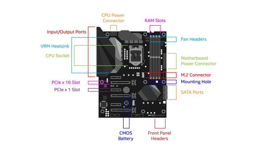
Description: Legacy expansion slots for connecting various peripheral cards.
Types: PCI, PCI-X (older), not commonly used in modern motherboards.
2. PCIe Slots (Peripheral Component Interconnect Express):
Description: High-speed expansion slots for graphics cards, sound cards, network cards, and other peripherals.
Types:
PCIe x16: Primary slot for graphics cards.
PCIe x1, PCIe x4, PCIe x8: Used for other expansion cards.
3. Power Connectors:
Description: Connectors providing power to the motherboard.
Types:
24-pin ATX Power Connector: Main power connector.
8-pin EPS Power Connector: Additional power for the CPU.
4. SATA Connectors (Serial ATA):
Description: Connectors for connecting SATA storage devices (HDDs, SSDs, optical drives).
Type: SATA III (6 Gb/s) is the common standard.
5. eSATA (External SATA) Connector:
Description: External SATA connector for connecting external storage devices.
Type: eSATA ports are less common on modern motherboards.
6. Headers:
Description: Internal connectors for various functions and peripherals.
Types:
USB Headers: Internal connectors for front/top panel USB ports.
Front Panel Headers: Connectors for power button, reset button, LEDs, etc.
Audio Headers: Connectors for front panel audio and additional audio features.
RGB Headers: Connectors for RGB LED lighting strips or devices.
7. M.2 Slots (M.2 Connector):
Description: Small, compact slots for M.2 storage devices or other M.2 modules.
Types:
M.2 Key M: For M.2 storage devices (NVMe SSDs).
M.2 Key B: For wireless networking cards.
M.2 Key E: For other expansion modules.
8. PCIe Power Connectors (for Graphics Cards):
Description: Connectors providing additional power to high-performance graphics cards.
Types:
6-pin PCIe Power Connector.
8-pin PCIe Power Connector.
6+2-pin PCIe Power Connector (combination of 6-pin and 2-pin).
Understanding these connectors is crucial when building or upgrading a computer, as it ensures compatibility between the motherboard and other components. It's also important to consider the power requirements of components like graphics cards, as they may need additional power connectors beyond what the motherboard provides.
154
Motherboard CPU Sockets
Motherboards come with different CPU sockets, and the choice of socket type determines the compatibility with specific processors. Here are some common CPU sockets found in modern motherboards:
1. LGA (Land Grid Array) Sockets:
LGA 1200:
Description: Used by Intel for 10th and 11th Gen Core processors (Comet Lake and Rocket Lake).
Common Motherboard Chipsets: Z490, B460, H410, etc.
LGA 1700:
Description: Introduced by Intel for 12th Gen Alder Lake processors.
Common Motherboard Chipsets: Z690, B660, H610, etc.
LGA 1151:
Description: Used by Intel for 6th, 7th, 8th, and 9th Gen Core processors.
Common Motherboard Chipsets: Z170, Z270, Z370, H310, B360, B365, etc.
LGA 2066:
Description: High-end socket for Intel Core X-Series processors.
Common Motherboard Chipsets: X299.
2. PGA (Pin Grid Array) Sockets:
PGA AM4:
Description: Used by AMD for Ryzen processors (1st Gen to current).
Common Motherboard Chipsets: B450, B550, X470, X570, A520, etc.
PGA TR4:
Description: High-end socket for AMD Ryzen Threadripper processors.
Common Motherboard Chipsets: X399.
PGA sTRX4:
Description: Used for AMD Ryzen Threadripper processors (3rd Gen).
Common Motherboard Chipsets: TRX40.
3. BGA (Ball Grid Array) Socket:
BGA Socket (Non-upgradable):
Description: Soldered directly onto the motherboard, not replaceable or upgradable.
Example: Some low-power and embedded CPUs, often found in ultrabooks and tablets.
4. **LGA 1200 and PGA AM4 are currently among the most common sockets for consumer desktop CPUs. When selecting a motherboard and CPU, it's crucial to ensure that the socket types match. Additionally, be aware of the specific chipset used by the motherboard, as it can influence features and compatibility with other components. Always refer to the motherboard's specifications and CPU compatibility list when planning a build or upgrade.
1. LGA (Land Grid Array) Sockets:
LGA 1200:
Description: Used by Intel for 10th and 11th Gen Core processors (Comet Lake and Rocket Lake).
Common Motherboard Chipsets: Z490, B460, H410, etc.
LGA 1700:
Description: Introduced by Intel for 12th Gen Alder Lake processors.
Common Motherboard Chipsets: Z690, B660, H610, etc.
LGA 1151:
Description: Used by Intel for 6th, 7th, 8th, and 9th Gen Core processors.
Common Motherboard Chipsets: Z170, Z270, Z370, H310, B360, B365, etc.
LGA 2066:
Description: High-end socket for Intel Core X-Series processors.
Common Motherboard Chipsets: X299.
2. PGA (Pin Grid Array) Sockets:
PGA AM4:
Description: Used by AMD for Ryzen processors (1st Gen to current).
Common Motherboard Chipsets: B450, B550, X470, X570, A520, etc.
PGA TR4:
Description: High-end socket for AMD Ryzen Threadripper processors.
Common Motherboard Chipsets: X399.
PGA sTRX4:
Description: Used for AMD Ryzen Threadripper processors (3rd Gen).
Common Motherboard Chipsets: TRX40.
3. BGA (Ball Grid Array) Socket:
BGA Socket (Non-upgradable):
Description: Soldered directly onto the motherboard, not replaceable or upgradable.
Example: Some low-power and embedded CPUs, often found in ultrabooks and tablets.
4. **LGA 1200 and PGA AM4 are currently among the most common sockets for consumer desktop CPUs. When selecting a motherboard and CPU, it's crucial to ensure that the socket types match. Additionally, be aware of the specific chipset used by the motherboard, as it can influence features and compatibility with other components. Always refer to the motherboard's specifications and CPU compatibility list when planning a build or upgrade.
155
Motherboard compatability with Severs, multisocket, desktop, and mobile
Motherboard compatibility varies based on the intended use case, socket type, and form factor. Here's an overview of motherboard compatibility with different scenarios: server, multi-socket, desktop, and mobile.
1. Server Motherboards:
Purpose: Designed for use in server environments with an emphasis on stability, reliability, and support for server-class components.
Key Features:
Typically supports server-class CPUs (e.g., Intel Xeon, AMD EPYC).
ECC (Error-Correcting Code) memory support for data integrity.
Multiple PCIe slots for expansion cards.
Remote management features (IPMI, iDRAC) for remote monitoring and control.
Server-oriented form factors such as ATX, Extended ATX (EATX), or proprietary server form factors.
2. Multi-Socket Motherboards:
Purpose: Designed to accommodate multiple CPUs on a single motherboard, providing increased processing power.
Key Features:
Supports multiple CPUs (e.g., dual-socket or quad-socket configurations).
Scalable memory support to handle increased processing demands.
Often used in high-performance computing (HPC) or enterprise server applications.
Larger form factors to accommodate multiple CPU sockets.
3. Desktop Motherboards:
Purpose: Designed for consumer desktop computers, gaming systems, and workstations.
Key Features:
Supports consumer-grade CPUs (e.g., Intel Core, AMD Ryzen).
Designed for single-CPU configurations.
Emphasizes features like gaming support, high-speed connectivity, and audio enhancements.
Form factors include ATX, Micro-ATX, and Mini-ITX.
4. Mobile Motherboards:
Purpose: Used in laptops, notebooks, and other portable devices.
Key Features:
Compact form factors to fit into slim and lightweight devices.
Integrated components to conserve space and power.
Typically not user-upgradable as components are soldered onto the motherboard.
Features vary based on the device type and intended use.
Compatibility Considerations:
CPU Socket Compatibility:
Different CPUs require specific socket types. Ensure the motherboard's socket matches the CPU socket.
Form Factor Compatibility:
Check the motherboard form factor to ensure it fits into the intended chassis.
Chipset Compatibility:
The motherboard chipset influences features and capabilities. Verify compatibility with your requirements.
Operating System Compatibility:
Ensure the motherboard supports the operating system you intend to use (e.g., Windows, Linux).
Memory Compatibility:
Check memory support, including type, speed, and maximum capacity.
Whether building a server, a multi-socket system, a desktop PC, or a mobile device, understanding motherboard compatibility is crucial. It ensures proper integration of components and optimal performance for the intended use case. Always refer to the motherboard's specifications and compatibility lists provided by the manufacturer.
1. Server Motherboards:
Purpose: Designed for use in server environments with an emphasis on stability, reliability, and support for server-class components.
Key Features:
Typically supports server-class CPUs (e.g., Intel Xeon, AMD EPYC).
ECC (Error-Correcting Code) memory support for data integrity.
Multiple PCIe slots for expansion cards.
Remote management features (IPMI, iDRAC) for remote monitoring and control.
Server-oriented form factors such as ATX, Extended ATX (EATX), or proprietary server form factors.
2. Multi-Socket Motherboards:
Purpose: Designed to accommodate multiple CPUs on a single motherboard, providing increased processing power.
Key Features:
Supports multiple CPUs (e.g., dual-socket or quad-socket configurations).
Scalable memory support to handle increased processing demands.
Often used in high-performance computing (HPC) or enterprise server applications.
Larger form factors to accommodate multiple CPU sockets.
3. Desktop Motherboards:
Purpose: Designed for consumer desktop computers, gaming systems, and workstations.
Key Features:
Supports consumer-grade CPUs (e.g., Intel Core, AMD Ryzen).
Designed for single-CPU configurations.
Emphasizes features like gaming support, high-speed connectivity, and audio enhancements.
Form factors include ATX, Micro-ATX, and Mini-ITX.
4. Mobile Motherboards:
Purpose: Used in laptops, notebooks, and other portable devices.
Key Features:
Compact form factors to fit into slim and lightweight devices.
Integrated components to conserve space and power.
Typically not user-upgradable as components are soldered onto the motherboard.
Features vary based on the device type and intended use.
Compatibility Considerations:
CPU Socket Compatibility:
Different CPUs require specific socket types. Ensure the motherboard's socket matches the CPU socket.
Form Factor Compatibility:
Check the motherboard form factor to ensure it fits into the intended chassis.
Chipset Compatibility:
The motherboard chipset influences features and capabilities. Verify compatibility with your requirements.
Operating System Compatibility:
Ensure the motherboard supports the operating system you intend to use (e.g., Windows, Linux).
Memory Compatibility:
Check memory support, including type, speed, and maximum capacity.
Whether building a server, a multi-socket system, a desktop PC, or a mobile device, understanding motherboard compatibility is crucial. It ensures proper integration of components and optimal performance for the intended use case. Always refer to the motherboard's specifications and compatibility lists provided by the manufacturer.
156
BIOS & UEFI
BIOS (Basic Input/Output System):
Role:
BIOS is firmware that initializes and manages hardware components during the computer's boot process.
It provides a basic set of instructions for the computer to start up and load the operating system.
Interface:
Typically uses a text-based interface.
Navigated using keyboard commands.
Functionality:
Manages the boot order of devices (e.g., hard drive, USB, optical drive).
Contains basic settings for hardware configuration (CPU, memory, etc.).
Limited support for modern features like mouse input and graphical interfaces.
Legacy:
Older technology that has been widely used for decades.
UEFI (Unified Extensible Firmware Interface):
Role:
UEFI is a modern firmware interface that serves the same purpose as BIOS but with added features.
It provides a standardized way for the operating system to interact with the firmware.
Interface:
Supports both text-based and graphical interfaces.
Often provides a more user-friendly experience.
Functionality:
Manages the boot process and boot order like BIOS.
Supports larger hard drives and more partitions.
Allows secure boot to ensure the integrity of the operating system.
Enables mouse support and a graphical user interface for easier navigation.
Can be updated and extended with additional features.
Advantages:
Faster boot times.
More advanced configurations and settings.
Enhanced security features like Secure Boot.
Key Takeaways:
BIOS: Traditional, text-based, and widely used. Basic functionality for booting and hardware configuration.
UEFI: Modern, supports both text and graphical interfaces. More advanced features, including secure boot and larger storage support.
Transition: Many systems have transitioned from BIOS to UEFI due to its advantages in terms of features and compatibility with modern hardware.
In summary, both BIOS and UEFI serve as firmware interfaces responsible for initiating the computer's hardware and booting the operating system. UEFI builds upon the functionality of BIOS and offers additional features and improvements, providing a more versatile and user-friendly experience.
Role:
BIOS is firmware that initializes and manages hardware components during the computer's boot process.
It provides a basic set of instructions for the computer to start up and load the operating system.
Interface:
Typically uses a text-based interface.
Navigated using keyboard commands.
Functionality:
Manages the boot order of devices (e.g., hard drive, USB, optical drive).
Contains basic settings for hardware configuration (CPU, memory, etc.).
Limited support for modern features like mouse input and graphical interfaces.
Legacy:
Older technology that has been widely used for decades.
UEFI (Unified Extensible Firmware Interface):
Role:
UEFI is a modern firmware interface that serves the same purpose as BIOS but with added features.
It provides a standardized way for the operating system to interact with the firmware.
Interface:
Supports both text-based and graphical interfaces.
Often provides a more user-friendly experience.
Functionality:
Manages the boot process and boot order like BIOS.
Supports larger hard drives and more partitions.
Allows secure boot to ensure the integrity of the operating system.
Enables mouse support and a graphical user interface for easier navigation.
Can be updated and extended with additional features.
Advantages:
Faster boot times.
More advanced configurations and settings.
Enhanced security features like Secure Boot.
Key Takeaways:
BIOS: Traditional, text-based, and widely used. Basic functionality for booting and hardware configuration.
UEFI: Modern, supports both text and graphical interfaces. More advanced features, including secure boot and larger storage support.
Transition: Many systems have transitioned from BIOS to UEFI due to its advantages in terms of features and compatibility with modern hardware.
In summary, both BIOS and UEFI serve as firmware interfaces responsible for initiating the computer's hardware and booting the operating system. UEFI builds upon the functionality of BIOS and offers additional features and improvements, providing a more versatile and user-friendly experience.
157
BIOS & UEFI Settings
Let's explore the simplified aspects of BIOS and UEFI boot options, USB permissions, TPM (Trusted Platform Module) security features, fan considerations, secure boot, and boot password:
1. Boot Options (BIOS/UEFI):
BIOS:
Boot options are configured in a text-based interface.
You can set the boot order to specify which device the computer should boot from first (e.g., hard drive, USB, optical drive).
UEFI:
Offers a more user-friendly interface with graphical options.
Allows you to configure the boot order and additional boot parameters.
2. USB Permissions:
BIOS:
Basic BIOS may not have specific USB permissions.
USB functionality is generally controlled by the operating system.
UEFI:
UEFI may include more advanced USB control features.
Secure Boot in UEFI helps prevent unauthorized USB devices from running during the boot process.
3. TPM Security Features:
BIOS:
Limited or no native support for TPM.
Security features are often handled by the operating system.
UEFI:
Supports TPM for hardware-based security.
Enables features like BitLocker for disk encryption.
4. Fan Considerations:
BIOS:
Basic fan control settings may be available.
Fan speeds might be adjusted through manual configuration.
UEFI:
UEFI often provides more advanced fan control.
Allows for temperature-based fan speed adjustments.
5. Secure Boot:
BIOS:
Limited or no support for Secure Boot.
Secure Boot is a UEFI feature.
UEFI:
Supports Secure Boot, ensuring that only signed and authenticated firmware and OS components are loaded during boot.
Enhances system security by preventing the loading of unauthorized code.
6. Boot Password:
BIOS:
Allows setting a basic boot password.
Security options may vary.
UEFI:
Offers more advanced boot password features.
May include additional security measures such as fingerprint or PIN authentication.
Key Considerations:
Transition:
Many modern systems use UEFI due to its advanced features and compatibility.
Transitioning from BIOS to UEFI may involve specific steps and considerations.
Security:
UEFI provides enhanced security features, such as Secure Boot and TPM support.
Secure Boot helps protect against malware during the boot process.
Ease of Use:
UEFI often provides a more user-friendly interface with graphical options.
BIOS interfaces are typically text-based and may have a steeper learning curve.
Remember that the specifics of these features can vary between different motherboard manufacturers and models. Always refer to the documentation provided by the motherboard manufacturer for detailed instructions and information on these features.
1. Boot Options (BIOS/UEFI):
BIOS:
Boot options are configured in a text-based interface.
You can set the boot order to specify which device the computer should boot from first (e.g., hard drive, USB, optical drive).
UEFI:
Offers a more user-friendly interface with graphical options.
Allows you to configure the boot order and additional boot parameters.
2. USB Permissions:
BIOS:
Basic BIOS may not have specific USB permissions.
USB functionality is generally controlled by the operating system.
UEFI:
UEFI may include more advanced USB control features.
Secure Boot in UEFI helps prevent unauthorized USB devices from running during the boot process.
3. TPM Security Features:
BIOS:
Limited or no native support for TPM.
Security features are often handled by the operating system.
UEFI:
Supports TPM for hardware-based security.
Enables features like BitLocker for disk encryption.
4. Fan Considerations:
BIOS:
Basic fan control settings may be available.
Fan speeds might be adjusted through manual configuration.
UEFI:
UEFI often provides more advanced fan control.
Allows for temperature-based fan speed adjustments.
5. Secure Boot:
BIOS:
Limited or no support for Secure Boot.
Secure Boot is a UEFI feature.
UEFI:
Supports Secure Boot, ensuring that only signed and authenticated firmware and OS components are loaded during boot.
Enhances system security by preventing the loading of unauthorized code.
6. Boot Password:
BIOS:
Allows setting a basic boot password.
Security options may vary.
UEFI:
Offers more advanced boot password features.
May include additional security measures such as fingerprint or PIN authentication.
Key Considerations:
Transition:
Many modern systems use UEFI due to its advanced features and compatibility.
Transitioning from BIOS to UEFI may involve specific steps and considerations.
Security:
UEFI provides enhanced security features, such as Secure Boot and TPM support.
Secure Boot helps protect against malware during the boot process.
Ease of Use:
UEFI often provides a more user-friendly interface with graphical options.
BIOS interfaces are typically text-based and may have a steeper learning curve.
Remember that the specifics of these features can vary between different motherboard manufacturers and models. Always refer to the documentation provided by the motherboard manufacturer for detailed instructions and information on these features.
158
Encryption
Encryption involving TPM (Trusted Platform Module) and HSM (Hardware Security Module) are two different approaches to securing sensitive data. Let's explore each of them:
TPM (Trusted Platform Module):
Role:
TPM is a dedicated microcontroller that provides a secure foundation for various security-related functions.
It's integrated into the motherboard and is designed to secure and store cryptographic keys, among other security tasks.
Key Functions:
Secure Key Storage: TPM can securely store encryption keys, ensuring they are not easily accessible by software or attackers.
Device Authentication: It can be used to authenticate the device, ensuring that it has not been tampered with.
Secure Boot: TPM plays a role in verifying the integrity of the boot process, ensuring that only trusted components are loaded.
Encryption Process:
When data is encrypted with TPM, cryptographic keys are securely stored within the TPM chip.
The decryption process involves the TPM releasing the key only if certain conditions (e.g., secure boot, device integrity) are met.
Use Cases:
Commonly used in device-level security, especially in enterprise environments.
Used in conjunction with encryption software to enhance overall system security.
HSM (Hardware Security Module):
Role:
HSM is a dedicated hardware device designed to manage and safeguard digital keys and perform cryptographic operations.
It provides a high level of security for sensitive operations such as key generation, storage, and encryption.
Key Functions:
Key Generation and Storage: HSMs generate and securely store cryptographic keys.
Cryptographic Operations: They perform cryptographic functions, including encryption, decryption, and digital signatures.
Secure Key Management: HSMs offer advanced key management features, such as key rotation and access controls.
Encryption Process:
When data is encrypted with an HSM, the cryptographic keys are generated and managed within the secure confines of the HSM.
The HSM performs encryption and decryption operations, ensuring the security of the keys and the cryptographic processes.
Use Cases:
Widely used in financial institutions, payment processing, and industries with stringent security requirements.
Often employed in scenarios where a high level of assurance and regulatory compliance is necessary.
Comparison:
Integration:
TPM is typically integrated into the motherboard of devices, providing a foundation for system-level security.
HSM is a separate, dedicated hardware device that can be added to a network or system as an external security module.
Scope:
TPM is often used for device-level security and system integrity.
HSM has a broader scope, often used in enterprise environments for managing cryptographic keys and securing various operations.
Use Case Considerations:
TPM is commonly found in consumer and enterprise devices.
HSM is chosen in scenarios where a higher level of security assurance and compliance is required.
In summary, TPM and HSM serve distinct purposes in the realm of security. TPM is more focused on device integrity and system-level security, while HSM provides a comprehensive solution for managing cryptographic keys and performing secure cryptographic operations in enterprise environments. The choice between them depends on specific use case requirements and security objectives.
TPM (Trusted Platform Module):
Role:
TPM is a dedicated microcontroller that provides a secure foundation for various security-related functions.
It's integrated into the motherboard and is designed to secure and store cryptographic keys, among other security tasks.
Key Functions:
Secure Key Storage: TPM can securely store encryption keys, ensuring they are not easily accessible by software or attackers.
Device Authentication: It can be used to authenticate the device, ensuring that it has not been tampered with.
Secure Boot: TPM plays a role in verifying the integrity of the boot process, ensuring that only trusted components are loaded.
Encryption Process:
When data is encrypted with TPM, cryptographic keys are securely stored within the TPM chip.
The decryption process involves the TPM releasing the key only if certain conditions (e.g., secure boot, device integrity) are met.
Use Cases:
Commonly used in device-level security, especially in enterprise environments.
Used in conjunction with encryption software to enhance overall system security.
HSM (Hardware Security Module):
Role:
HSM is a dedicated hardware device designed to manage and safeguard digital keys and perform cryptographic operations.
It provides a high level of security for sensitive operations such as key generation, storage, and encryption.
Key Functions:
Key Generation and Storage: HSMs generate and securely store cryptographic keys.
Cryptographic Operations: They perform cryptographic functions, including encryption, decryption, and digital signatures.
Secure Key Management: HSMs offer advanced key management features, such as key rotation and access controls.
Encryption Process:
When data is encrypted with an HSM, the cryptographic keys are generated and managed within the secure confines of the HSM.
The HSM performs encryption and decryption operations, ensuring the security of the keys and the cryptographic processes.
Use Cases:
Widely used in financial institutions, payment processing, and industries with stringent security requirements.
Often employed in scenarios where a high level of assurance and regulatory compliance is necessary.
Comparison:
Integration:
TPM is typically integrated into the motherboard of devices, providing a foundation for system-level security.
HSM is a separate, dedicated hardware device that can be added to a network or system as an external security module.
Scope:
TPM is often used for device-level security and system integrity.
HSM has a broader scope, often used in enterprise environments for managing cryptographic keys and securing various operations.
Use Case Considerations:
TPM is commonly found in consumer and enterprise devices.
HSM is chosen in scenarios where a higher level of security assurance and compliance is required.
In summary, TPM and HSM serve distinct purposes in the realm of security. TPM is more focused on device integrity and system-level security, while HSM provides a comprehensive solution for managing cryptographic keys and performing secure cryptographic operations in enterprise environments. The choice between them depends on specific use case requirements and security objectives.
159
CPU Architecture
CPU architecture refers to the design and structure of a computer's central processing unit (CPU). Common CPU architectures include x64/x86, ARM, and specific features like single-core, multicore, multithreading, and virtualization support.
1. x64/x86 Architecture:
x86:
Refers to a family of CPU architectures based on the Intel 8086 CPU.
Commonly used in personal computers and servers.
x86 processors have a 32-bit instruction set architecture.
x64 (64-bit x86):
Extends x86 to 64 bits, allowing for larger memory addressing and improved performance.
Most modern desktops, laptops, and servers use x64 architecture.
x64 processors can run both 32-bit and 64-bit applications.
2. ARM Architecture:
ARM: Advanced RISC Machine
Designed by ARM Holdings and widely used in mobile devices, embedded systems, and increasingly in servers.
Known for its energy efficiency and power consumption, making it suitable for portable devices.
ARM processors have different instruction set architectures, such as ARMv7 and ARMv8.
3. Single Core, Multicore, Multithreading:
Single Core:
A CPU with a single processing core.
Executes one instruction at a time.
Multicore:
CPU with multiple independent processing cores on a single chip.
Allows parallel execution of tasks, improving overall performance.
Multithreading:
Technique where each core can execute multiple threads simultaneously.
Enhances parallelism, improving system responsiveness.
4. Virtualization Support:
Virtualization:
Technology that allows multiple operating systems to run on a single physical machine.
Creates virtual environments (virtual machines) for running guest operating systems.
Virtualization Support Features:
Intel VT-x (Virtualization Technology): Found in Intel processors.
AMD-V (AMD Virtualization): Found in AMD processors.
Enhances the efficiency and performance of virtual machines.
Summary:
Use Cases:
x86/x64: Common in desktops, laptops, and servers.
ARM: Predominantly used in mobile devices, embedded systems, and increasingly in servers.
Performance:
x64 provides 64-bit addressing and improved performance.
ARM is known for energy efficiency and power consumption.
Core Architecture:
Single Core: Executes one instruction at a time.
Multicore: Multiple independent processing cores on a single chip.
Multithreading: Each core can execute multiple threads simultaneously.
Virtualization:
Virtualization support (VT-x, AMD-V) enhances the efficiency of virtual machines.
Understanding CPU architecture is crucial when selecting hardware for specific applications, as different architectures excel in various use cases based on factors like power efficiency, performance, and compatibility.
1. x64/x86 Architecture:
x86:
Refers to a family of CPU architectures based on the Intel 8086 CPU.
Commonly used in personal computers and servers.
x86 processors have a 32-bit instruction set architecture.
x64 (64-bit x86):
Extends x86 to 64 bits, allowing for larger memory addressing and improved performance.
Most modern desktops, laptops, and servers use x64 architecture.
x64 processors can run both 32-bit and 64-bit applications.
2. ARM Architecture:
ARM: Advanced RISC Machine
Designed by ARM Holdings and widely used in mobile devices, embedded systems, and increasingly in servers.
Known for its energy efficiency and power consumption, making it suitable for portable devices.
ARM processors have different instruction set architectures, such as ARMv7 and ARMv8.
3. Single Core, Multicore, Multithreading:
Single Core:
A CPU with a single processing core.
Executes one instruction at a time.
Multicore:
CPU with multiple independent processing cores on a single chip.
Allows parallel execution of tasks, improving overall performance.
Multithreading:
Technique where each core can execute multiple threads simultaneously.
Enhances parallelism, improving system responsiveness.
4. Virtualization Support:
Virtualization:
Technology that allows multiple operating systems to run on a single physical machine.
Creates virtual environments (virtual machines) for running guest operating systems.
Virtualization Support Features:
Intel VT-x (Virtualization Technology): Found in Intel processors.
AMD-V (AMD Virtualization): Found in AMD processors.
Enhances the efficiency and performance of virtual machines.
Summary:
Use Cases:
x86/x64: Common in desktops, laptops, and servers.
ARM: Predominantly used in mobile devices, embedded systems, and increasingly in servers.
Performance:
x64 provides 64-bit addressing and improved performance.
ARM is known for energy efficiency and power consumption.
Core Architecture:
Single Core: Executes one instruction at a time.
Multicore: Multiple independent processing cores on a single chip.
Multithreading: Each core can execute multiple threads simultaneously.
Virtualization:
Virtualization support (VT-x, AMD-V) enhances the efficiency of virtual machines.
Understanding CPU architecture is crucial when selecting hardware for specific applications, as different architectures excel in various use cases based on factors like power efficiency, performance, and compatibility.
160
Expansion Cards
Expansion cards are additional hardware components that can be added to a computer's motherboard to enhance its capabilities. Here are four types of expansion cards: sound card, video card (graphics card), capture card, and network interface card (NIC):
1. Sound Card:
Functionality:
Adds audio processing capabilities to a computer.
Improves sound quality for audio playback, recording, and multimedia applications.
Usage:
Ideal for users who require better audio performance than what is provided by the integrated audio on the motherboard.
Commonly used by audiophiles, content creators, and gamers for high-quality sound output.
Connectivity:
Connects to a PCI, PCIe, or USB slot on the motherboard.
May include inputs and outputs for speakers, headphones, microphones, and other audio devices.
2. Video Card (Graphics Card):
Functionality:
Enhances graphics and video processing capabilities.
Provides dedicated graphical processing units (GPUs) for rendering images, videos, and 3D graphics.
Usage:
Essential for gaming, video editing, graphic design, and any graphics-intensive applications.
Improves overall system performance by offloading graphical tasks from the CPU.
Connectivity:
Connects to a PCI, PCIe, or AGP slot on the motherboard.
Offers video outputs such as HDMI, DisplayPort, DVI, or VGA for connecting to monitors or displays.
3. Capture Card:
Functionality:
Captures and records audio and video signals from external sources.
Used for capturing gameplay, streaming, video editing, or recording from devices like cameras and consoles.
Usage:
Popular among content creators, streamers, and gamers who want to capture and share their gameplay or create professional video content.
Connectivity:
Connects to a PCIe slot or USB port on the motherboard.
May have various input ports such as HDMI, component, or composite for connecting external devices.
4. Network Interface Card (NIC):
Functionality:
Provides network connectivity to a computer.
Facilitates communication over a network by converting data between the computer and the network.
Usage:
Used to enable wired or wireless network connectivity.
Essential for accessing the internet, local area networks (LANs), or connecting to other devices.
Connectivity:
Wired NIC: Connects to a PCI or PCIe slot and uses Ethernet ports.
Wireless NIC: Connects via PCIe or USB and provides Wi-Fi connectivity.
Considerations:
Compatibility:
Ensure compatibility with the motherboard's slot type (PCI, PCIe) and available slots.
Drivers:
Install the necessary drivers for the expansion cards to ensure proper functionality.
Power Requirements:
High-performance cards may require additional power connectors.
Space:
Consider the physical space inside the computer case to accommodate the expansion cards.
Adding expansion cards allows users to customize and upgrade their systems based on specific needs, enhancing performance and functionality.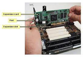
1. Sound Card:
Functionality:
Adds audio processing capabilities to a computer.
Improves sound quality for audio playback, recording, and multimedia applications.
Usage:
Ideal for users who require better audio performance than what is provided by the integrated audio on the motherboard.
Commonly used by audiophiles, content creators, and gamers for high-quality sound output.
Connectivity:
Connects to a PCI, PCIe, or USB slot on the motherboard.
May include inputs and outputs for speakers, headphones, microphones, and other audio devices.
2. Video Card (Graphics Card):
Functionality:
Enhances graphics and video processing capabilities.
Provides dedicated graphical processing units (GPUs) for rendering images, videos, and 3D graphics.
Usage:
Essential for gaming, video editing, graphic design, and any graphics-intensive applications.
Improves overall system performance by offloading graphical tasks from the CPU.
Connectivity:
Connects to a PCI, PCIe, or AGP slot on the motherboard.
Offers video outputs such as HDMI, DisplayPort, DVI, or VGA for connecting to monitors or displays.
3. Capture Card:
Functionality:
Captures and records audio and video signals from external sources.
Used for capturing gameplay, streaming, video editing, or recording from devices like cameras and consoles.
Usage:
Popular among content creators, streamers, and gamers who want to capture and share their gameplay or create professional video content.
Connectivity:
Connects to a PCIe slot or USB port on the motherboard.
May have various input ports such as HDMI, component, or composite for connecting external devices.
4. Network Interface Card (NIC):
Functionality:
Provides network connectivity to a computer.
Facilitates communication over a network by converting data between the computer and the network.
Usage:
Used to enable wired or wireless network connectivity.
Essential for accessing the internet, local area networks (LANs), or connecting to other devices.
Connectivity:
Wired NIC: Connects to a PCI or PCIe slot and uses Ethernet ports.
Wireless NIC: Connects via PCIe or USB and provides Wi-Fi connectivity.
Considerations:
Compatibility:
Ensure compatibility with the motherboard's slot type (PCI, PCIe) and available slots.
Drivers:
Install the necessary drivers for the expansion cards to ensure proper functionality.
Power Requirements:
High-performance cards may require additional power connectors.
Space:
Consider the physical space inside the computer case to accommodate the expansion cards.
Adding expansion cards allows users to customize and upgrade their systems based on specific needs, enhancing performance and functionality.
161
Cooling
Cooling components are crucial for managing the temperature of computer hardware and preventing overheating. Here are some key cooling components: cooling fans, heat sinks, thermal paste/pads, and liquid cooling.
1. Cooling Fans:
Functionality:
Cooling fans dissipate heat by moving air through or around components.
Commonly used to cool the CPU, GPU, and other heat-generating components.
Varieties:
Case Fans: Installed in the computer case to improve overall airflow.
CPU Fans: Dedicated fans for cooling the CPU heatsink.
GPU Fans: Integrated fans on graphics cards for cooling.
Sizes and Mounting:
Common sizes include 120mm and 140mm.
Mounted on case walls, CPU coolers, or graphics cards.
2. Heat Sink:
Functionality:
Heat sinks are metal components that absorb and disperse heat away from hot surfaces.
Often used in conjunction with fans to enhance cooling efficiency.
Materials:
Typically made of aluminum or copper due to their high thermal conductivity.
May have fins or other structures to increase surface area for better heat dissipation.
Applications:
Found on CPUs, GPUs, and other components with high heat generation.
3. Thermal Paste/Pads:
Functionality:
Thermal paste (or thermal compound) fills microscopic gaps between the heat sink and the component's surface.
Enhances the thermal conductivity, ensuring efficient heat transfer.
Application:
Applied between the CPU/GPU and the heat sink.
Ensures a proper thermal interface for improved cooling.
Types:
Paste: Applied using a syringe or applicator.
Pads: Pre-applied or thermal pads are alternative options for specific applications.
4. Liquid Cooling:
Functionality:
Liquid cooling systems use a closed loop or custom-designed setups to circulate liquid coolant.
Effective at dissipating heat from components.
Components:
CPU/GPU Blocks: Transfer heat from the component to the liquid.
Radiator: Dissipates heat from the liquid to the surrounding air.
Pump: Circulates the liquid through the system.
Advantages:
Efficient cooling, especially for overclocked components.
Reduced noise compared to some air cooling solutions.
Considerations:
Compatibility:
Ensure compatibility with the specific CPU/GPU socket or component.
Airflow:
Optimize case and component placement for optimal airflow.
Maintenance:
Regularly clean fans and heatsinks to prevent dust buildup.
Installation:
Follow manufacturer guidelines for proper installation of thermal paste, pads, and liquid cooling components.
Each cooling component plays a role in maintaining the temperature of critical computer hardware. The choice of cooling solutions depends on factors like system requirements, thermal demands, and user preferences.
1. Cooling Fans:
Functionality:
Cooling fans dissipate heat by moving air through or around components.
Commonly used to cool the CPU, GPU, and other heat-generating components.
Varieties:
Case Fans: Installed in the computer case to improve overall airflow.
CPU Fans: Dedicated fans for cooling the CPU heatsink.
GPU Fans: Integrated fans on graphics cards for cooling.
Sizes and Mounting:
Common sizes include 120mm and 140mm.
Mounted on case walls, CPU coolers, or graphics cards.
2. Heat Sink:
Functionality:
Heat sinks are metal components that absorb and disperse heat away from hot surfaces.
Often used in conjunction with fans to enhance cooling efficiency.
Materials:
Typically made of aluminum or copper due to their high thermal conductivity.
May have fins or other structures to increase surface area for better heat dissipation.
Applications:
Found on CPUs, GPUs, and other components with high heat generation.
3. Thermal Paste/Pads:
Functionality:
Thermal paste (or thermal compound) fills microscopic gaps between the heat sink and the component's surface.
Enhances the thermal conductivity, ensuring efficient heat transfer.
Application:
Applied between the CPU/GPU and the heat sink.
Ensures a proper thermal interface for improved cooling.
Types:
Paste: Applied using a syringe or applicator.
Pads: Pre-applied or thermal pads are alternative options for specific applications.
4. Liquid Cooling:
Functionality:
Liquid cooling systems use a closed loop or custom-designed setups to circulate liquid coolant.
Effective at dissipating heat from components.
Components:
CPU/GPU Blocks: Transfer heat from the component to the liquid.
Radiator: Dissipates heat from the liquid to the surrounding air.
Pump: Circulates the liquid through the system.
Advantages:
Efficient cooling, especially for overclocked components.
Reduced noise compared to some air cooling solutions.
Considerations:
Compatibility:
Ensure compatibility with the specific CPU/GPU socket or component.
Airflow:
Optimize case and component placement for optimal airflow.
Maintenance:
Regularly clean fans and heatsinks to prevent dust buildup.
Installation:
Follow manufacturer guidelines for proper installation of thermal paste, pads, and liquid cooling components.
Each cooling component plays a role in maintaining the temperature of critical computer hardware. The choice of cooling solutions depends on factors like system requirements, thermal demands, and user preferences.
162
INPUT Power Supply
The terms "110-220 VAC" and "220-240 VAC" refer to different voltage ranges for electrical systems. Here's an explanation of each:
1. 110-220 VAC:
Voltage Range:
This indicates a voltage range that includes both 110 volts and 220 volts AC (Alternating Current).
It is commonly associated with electrical systems that support dual voltage, catering to both 110V and 220V devices.
Usage:
Commonly found in regions where electrical systems support both lower voltage devices (110V) and higher voltage devices (220V).
It allows flexibility for devices that can operate within this range.
Examples:
Some electronic devices, power tools, or appliances may have dual voltage capability, allowing them to work within the 110-220 VAC range.
2. 220-240 VAC:
Voltage Range:
This indicates a voltage range that includes voltages between 220 volts and 240 volts AC.
It is a standard voltage range in many countries for household electrical systems.
Usage:
Commonly found in regions where the standard household voltage is higher (e.g., Europe, Asia, Africa).
Many household appliances and electronic devices in these regions are designed to operate within the 220-240 VAC range.
Examples:
Household appliances like refrigerators, washing machines, and ovens in countries with a 220-240 VAC standard.
Considerations:
Voltage Compatibility:
Devices and appliances should be compatible with the voltage provided by the electrical system in the region where they are used.
Dual Voltage Devices:
Some devices are designed to be dual voltage, meaning they can operate in both 110-220 VAC and 220-240 VAC systems. Check the device's specifications and labels.
Voltage Adapters/Converters:
When traveling between regions with different voltage standards, voltage adapters or converters may be necessary to ensure the correct voltage for your devices.
Always refer to the device's specifications or user manual to determine its voltage requirements and compatibility. Using devices with incorrect voltage settings can lead to damage and pose safety risks.
1. 110-220 VAC:
Voltage Range:
This indicates a voltage range that includes both 110 volts and 220 volts AC (Alternating Current).
It is commonly associated with electrical systems that support dual voltage, catering to both 110V and 220V devices.
Usage:
Commonly found in regions where electrical systems support both lower voltage devices (110V) and higher voltage devices (220V).
It allows flexibility for devices that can operate within this range.
Examples:
Some electronic devices, power tools, or appliances may have dual voltage capability, allowing them to work within the 110-220 VAC range.
2. 220-240 VAC:
Voltage Range:
This indicates a voltage range that includes voltages between 220 volts and 240 volts AC.
It is a standard voltage range in many countries for household electrical systems.
Usage:
Commonly found in regions where the standard household voltage is higher (e.g., Europe, Asia, Africa).
Many household appliances and electronic devices in these regions are designed to operate within the 220-240 VAC range.
Examples:
Household appliances like refrigerators, washing machines, and ovens in countries with a 220-240 VAC standard.
Considerations:
Voltage Compatibility:
Devices and appliances should be compatible with the voltage provided by the electrical system in the region where they are used.
Dual Voltage Devices:
Some devices are designed to be dual voltage, meaning they can operate in both 110-220 VAC and 220-240 VAC systems. Check the device's specifications and labels.
Voltage Adapters/Converters:
When traveling between regions with different voltage standards, voltage adapters or converters may be necessary to ensure the correct voltage for your devices.
Always refer to the device's specifications or user manual to determine its voltage requirements and compatibility. Using devices with incorrect voltage settings can lead to damage and pose safety risks.
163
OUTPUT Power Supply
The terms "3.3V," "5V," and "12V" refer to different voltage levels in electrical systems. These voltage levels are commonly used in various electronic devices and components. Here's an explanation of each:
1. 3.3V (Volts):
Voltage Level:
3.3V indicates a voltage level of 3.3 volts in an electrical system.
Usage:
Commonly used in low-power electronic devices, microcontrollers, and some digital components.
Provides a lower voltage for circuits that require less power.
Examples:
Many modern integrated circuits (ICs), sensors, and microcontrollers operate at 3.3V.
2. 5V (Volts):
Voltage Level:
5V indicates a voltage level of 5 volts in an electrical system.
Usage:
Widely used as a standard voltage level in digital circuits, microcontrollers, and various electronic components.
Commonly found in USB power supplies, some sensors, and certain digital logic circuits.
Examples:
USB power supplies typically provide 5V for charging and powering devices.
Many microcontrollers and digital ICs operate at 5V.
3. 12V (Volts):
Voltage Level:
12V indicates a voltage level of 12 volts in an electrical system.
Usage:
Commonly used in higher-power electronic devices, motors, and components that require more substantial power.
Found in power supplies for desktop computers, automotive systems, and some lighting applications.
Examples:
Desktop computer power supplies often provide a 12V rail for components such as fans and drives.
Automotive systems use 12V for various electrical components.
Considerations:
Compatibility:
Electronic devices and components should be connected to a power source that provides the correct voltage.
Power Requirements:
The choice of voltage depends on the power requirements of the specific components or devices.
Regulation:
Power supplies often have voltage regulation to ensure stable and accurate output voltages.
Safety:
Handling higher voltages requires proper safety precautions, especially when working with electrical systems.
Understanding the voltage requirements of electronic components is crucial for proper operation and preventing damage. Always check the specifications of devices and power supplies to ensure compatibility.
1. 3.3V (Volts):
Voltage Level:
3.3V indicates a voltage level of 3.3 volts in an electrical system.
Usage:
Commonly used in low-power electronic devices, microcontrollers, and some digital components.
Provides a lower voltage for circuits that require less power.
Examples:
Many modern integrated circuits (ICs), sensors, and microcontrollers operate at 3.3V.
2. 5V (Volts):
Voltage Level:
5V indicates a voltage level of 5 volts in an electrical system.
Usage:
Widely used as a standard voltage level in digital circuits, microcontrollers, and various electronic components.
Commonly found in USB power supplies, some sensors, and certain digital logic circuits.
Examples:
USB power supplies typically provide 5V for charging and powering devices.
Many microcontrollers and digital ICs operate at 5V.
3. 12V (Volts):
Voltage Level:
12V indicates a voltage level of 12 volts in an electrical system.
Usage:
Commonly used in higher-power electronic devices, motors, and components that require more substantial power.
Found in power supplies for desktop computers, automotive systems, and some lighting applications.
Examples:
Desktop computer power supplies often provide a 12V rail for components such as fans and drives.
Automotive systems use 12V for various electrical components.
Considerations:
Compatibility:
Electronic devices and components should be connected to a power source that provides the correct voltage.
Power Requirements:
The choice of voltage depends on the power requirements of the specific components or devices.
Regulation:
Power supplies often have voltage regulation to ensure stable and accurate output voltages.
Safety:
Handling higher voltages requires proper safety precautions, especially when working with electrical systems.
Understanding the voltage requirements of electronic components is crucial for proper operation and preventing damage. Always check the specifications of devices and power supplies to ensure compatibility.
164
20-Pin to 24-PIN Motherboard Adapter
A 20-pin to 24-pin motherboard adapter is a cable or connector that allows you to connect a power supply unit (PSU) with a 20-pin connector to a motherboard with a 24-pin power socket.
Here's an explanation of why such adapters are used:
Background:
Power Supply Connectors:
Power supplies typically come with either a 20-pin or 24-pin main power connector.
Older motherboards often have a 20-pin power socket, while newer ones have a 24-pin socket.
Compatibility Issue:
When upgrading or replacing a power supply, you may encounter a situation where the PSU has a 20-pin connector, but the motherboard requires a 24-pin connection.
Functionality:
Adapter Design:
The 20-pin to 24-pin adapter bridges the gap between the 20-pin PSU connector and the 24-pin motherboard socket.
It typically has a 20-pin male connector on one end and a 24-pin female connector on the other end.
Pin Configuration:
The adapter ensures that the essential power lines are connected correctly, allowing the motherboard to receive the necessary power.
Compatibility:
The adapter is designed to make a 20-pin PSU compatible with a 24-pin motherboard, ensuring the proper supply of power to the motherboard components.
Usage Scenarios:
Upgrade Scenarios:
When upgrading a system with an older PSU to a newer motherboard that requires a 24-pin connection.
Temporary Solutions:
In some cases, the adapter might be used temporarily until a new power supply with the correct connector is obtained.
Considerations:
Power Supply Capacity:
Ensure that the power supply has a sufficient wattage capacity for the components in your system.
Compatibility with Older Systems:
The use of adapters is more common in situations where older systems are being upgraded.
Long-Term Solution:
While adapters can provide a temporary solution, it's generally recommended to use a power supply with the appropriate native connector for long-term stability.
Important Note:
While adapters can be useful for addressing immediate compatibility issues, it's essential to consider the long-term stability and efficiency of your system. If possible, investing in a power supply with the correct native connector is preferable over relying on adapters, especially in high-performance systems. Always follow the manufacturer's guidelines and specifications for your motherboard and power supply to ensure compatibility and safe operation.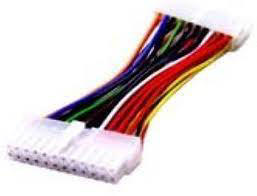
Here's an explanation of why such adapters are used:
Background:
Power Supply Connectors:
Power supplies typically come with either a 20-pin or 24-pin main power connector.
Older motherboards often have a 20-pin power socket, while newer ones have a 24-pin socket.
Compatibility Issue:
When upgrading or replacing a power supply, you may encounter a situation where the PSU has a 20-pin connector, but the motherboard requires a 24-pin connection.
Functionality:
Adapter Design:
The 20-pin to 24-pin adapter bridges the gap between the 20-pin PSU connector and the 24-pin motherboard socket.
It typically has a 20-pin male connector on one end and a 24-pin female connector on the other end.
Pin Configuration:
The adapter ensures that the essential power lines are connected correctly, allowing the motherboard to receive the necessary power.
Compatibility:
The adapter is designed to make a 20-pin PSU compatible with a 24-pin motherboard, ensuring the proper supply of power to the motherboard components.
Usage Scenarios:
Upgrade Scenarios:
When upgrading a system with an older PSU to a newer motherboard that requires a 24-pin connection.
Temporary Solutions:
In some cases, the adapter might be used temporarily until a new power supply with the correct connector is obtained.
Considerations:
Power Supply Capacity:
Ensure that the power supply has a sufficient wattage capacity for the components in your system.
Compatibility with Older Systems:
The use of adapters is more common in situations where older systems are being upgraded.
Long-Term Solution:
While adapters can provide a temporary solution, it's generally recommended to use a power supply with the appropriate native connector for long-term stability.
Important Note:
While adapters can be useful for addressing immediate compatibility issues, it's essential to consider the long-term stability and efficiency of your system. If possible, investing in a power supply with the correct native connector is preferable over relying on adapters, especially in high-performance systems. Always follow the manufacturer's guidelines and specifications for your motherboard and power supply to ensure compatibility and safe operation.
165
Redundant Power Supply
A redundant power supply is a configuration in which a computer or server system is equipped with more than one power supply unit (PSU). The primary purpose of redundant power supplies is to enhance system reliability and reduce the risk of power-related failures. Here's an overview of redundant power supplies:
Key Features:
Dual or More Power Supplies:
Redundant power supplies involve having two or more independent power supply units within the same system.
Continuous Power Supply:
If one power supply unit fails, the others continue to provide power, ensuring uninterrupted operation.
Automatic Failover:
Redundant power supplies typically include automatic failover mechanisms. If one PSU fails, the other(s) take over seamlessly.
Hot-Swappable:
Many redundant power supplies are hot-swappable, allowing for replacement without shutting down the system.
Increased Reliability:
Redundant power supplies enhance system reliability by mitigating the impact of power supply failures.
Critical for Mission-Critical Systems:
Commonly used in mission-critical environments where system uptime is crucial, such as data centers, servers, and enterprise-level applications.
Benefits:
Fault Tolerance:
Redundant power supplies provide fault tolerance by ensuring that the failure of one power supply does not result in a system shutdown.
Enhanced Uptime:
Systems with redundant power supplies experience minimal downtime, even in the event of a power supply failure.
Risk Mitigation:
Mitigates the risk of power-related failures impacting critical operations and data.
Scalability:
Redundant power supplies are scalable, allowing systems to be configured with the appropriate number of PSUs based on the level of redundancy required.
Considerations:
Cost:
Redundant power supply configurations may be more expensive due to the additional hardware.
Power Supply Compatibility:
Ensure that the redundant power supplies are compatible with the specific system and motherboard.
Load Balancing:
Distribute the load evenly among the redundant power supplies to maximize efficiency.
Regular Maintenance:
Conduct regular maintenance and testing to identify and address potential issues before they lead to failures.
Common Configurations:
N+1 Redundancy:
One additional power supply is added as a backup. If one fails, the others continue to operate.
2N Redundancy:
Each power supply is fully capable of handling the system's load. If one fails, the others can collectively support the entire load.
Redundant power supplies play a crucial role in ensuring the availability and reliability of critical systems. The specific configuration chosen depends on the level of redundancy required and the criticality of the system's operation.
Key Features:
Dual or More Power Supplies:
Redundant power supplies involve having two or more independent power supply units within the same system.
Continuous Power Supply:
If one power supply unit fails, the others continue to provide power, ensuring uninterrupted operation.
Automatic Failover:
Redundant power supplies typically include automatic failover mechanisms. If one PSU fails, the other(s) take over seamlessly.
Hot-Swappable:
Many redundant power supplies are hot-swappable, allowing for replacement without shutting down the system.
Increased Reliability:
Redundant power supplies enhance system reliability by mitigating the impact of power supply failures.
Critical for Mission-Critical Systems:
Commonly used in mission-critical environments where system uptime is crucial, such as data centers, servers, and enterprise-level applications.
Benefits:
Fault Tolerance:
Redundant power supplies provide fault tolerance by ensuring that the failure of one power supply does not result in a system shutdown.
Enhanced Uptime:
Systems with redundant power supplies experience minimal downtime, even in the event of a power supply failure.
Risk Mitigation:
Mitigates the risk of power-related failures impacting critical operations and data.
Scalability:
Redundant power supplies are scalable, allowing systems to be configured with the appropriate number of PSUs based on the level of redundancy required.
Considerations:
Cost:
Redundant power supply configurations may be more expensive due to the additional hardware.
Power Supply Compatibility:
Ensure that the redundant power supplies are compatible with the specific system and motherboard.
Load Balancing:
Distribute the load evenly among the redundant power supplies to maximize efficiency.
Regular Maintenance:
Conduct regular maintenance and testing to identify and address potential issues before they lead to failures.
Common Configurations:
N+1 Redundancy:
One additional power supply is added as a backup. If one fails, the others continue to operate.
2N Redundancy:
Each power supply is fully capable of handling the system's load. If one fails, the others can collectively support the entire load.
Redundant power supplies play a crucial role in ensuring the availability and reliability of critical systems. The specific configuration chosen depends on the level of redundancy required and the criticality of the system's operation.
166
Modular Power Supply
A modular power supply is a type of computer power supply unit (PSU) that offers flexibility in cable management by allowing users to connect only the cables they need. Unlike non-modular PSUs where all cables are permanently attached, modular PSUs provide detachable cables, enabling a cleaner and more organized build.
Here are the key features and benefits of modular power supplies:
Key Features:
Modularity:
Modular power supplies have detachable cables, allowing users to connect only the necessary cables for their specific hardware configuration.
Cable Management:
Enables better cable management and organization inside the computer case.
Reduces cable clutter, improving airflow and aesthetics.
Customization:
Users can customize their cable selection based on the components they have installed, reducing unused cables.
Upgradability:
Facilitates easy upgrades and changes in hardware configurations without dealing with a mess of unused cables.
Aesthetics:
Provides a cleaner and more visually appealing interior in the computer case.
Airflow Optimization:
Improved cable management allows for better airflow within the case, which can contribute to better cooling performance.
Ease of Maintenance:
Simplifies maintenance tasks, such as component upgrades or replacements, by allowing easy cable adjustments.
Types of Modular Power Supplies:
Fully Modular:
All cables, including those essential for powering the motherboard and CPU, are detachable. Users connect only the needed cables.
Semi-Modular:
Some essential cables, like those for the motherboard and CPU, are permanently attached, while peripheral cables (SATA, PCIe) are modular.
Considerations:
Cost:
Modular power supplies tend to be slightly more expensive than their non-modular counterparts due to the added feature.
Space Efficiency:
In smaller cases, the flexibility provided by modular cables can be particularly beneficial, as it allows for efficient use of available space.
Connector Compatibility:
Ensure that the modular power supply has the appropriate connectors for your components (e.g., PCIe connectors for graphics cards, SATA connectors for storage drives).
Power Rating:
Choose a modular power supply with an appropriate power rating (wattage) based on your system's requirements.
Common Applications:
Gaming PCs:
Modular power supplies are popular in gaming PCs, where users often have a variety of components and peripherals.
High-End Builds:
Enthusiast and high-performance builds benefit from the customization and cable management options provided by modular PSUs.
Aesthetically-Driven Builds:
Systems focused on aesthetics and showcasing components often use modular power supplies for a cleaner and more organized appearance.
In summary, modular power supplies offer flexibility and convenience for users who prioritize cable management, customization, and a clean interior layout in their computer builds. The choice between fully modular and semi-modular depends on individual preferences and specific system requirements.
Here are the key features and benefits of modular power supplies:
Key Features:
Modularity:
Modular power supplies have detachable cables, allowing users to connect only the necessary cables for their specific hardware configuration.
Cable Management:
Enables better cable management and organization inside the computer case.
Reduces cable clutter, improving airflow and aesthetics.
Customization:
Users can customize their cable selection based on the components they have installed, reducing unused cables.
Upgradability:
Facilitates easy upgrades and changes in hardware configurations without dealing with a mess of unused cables.
Aesthetics:
Provides a cleaner and more visually appealing interior in the computer case.
Airflow Optimization:
Improved cable management allows for better airflow within the case, which can contribute to better cooling performance.
Ease of Maintenance:
Simplifies maintenance tasks, such as component upgrades or replacements, by allowing easy cable adjustments.
Types of Modular Power Supplies:
Fully Modular:
All cables, including those essential for powering the motherboard and CPU, are detachable. Users connect only the needed cables.
Semi-Modular:
Some essential cables, like those for the motherboard and CPU, are permanently attached, while peripheral cables (SATA, PCIe) are modular.
Considerations:
Cost:
Modular power supplies tend to be slightly more expensive than their non-modular counterparts due to the added feature.
Space Efficiency:
In smaller cases, the flexibility provided by modular cables can be particularly beneficial, as it allows for efficient use of available space.
Connector Compatibility:
Ensure that the modular power supply has the appropriate connectors for your components (e.g., PCIe connectors for graphics cards, SATA connectors for storage drives).
Power Rating:
Choose a modular power supply with an appropriate power rating (wattage) based on your system's requirements.
Common Applications:
Gaming PCs:
Modular power supplies are popular in gaming PCs, where users often have a variety of components and peripherals.
High-End Builds:
Enthusiast and high-performance builds benefit from the customization and cable management options provided by modular PSUs.
Aesthetically-Driven Builds:
Systems focused on aesthetics and showcasing components often use modular power supplies for a cleaner and more organized appearance.
In summary, modular power supplies offer flexibility and convenience for users who prioritize cable management, customization, and a clean interior layout in their computer builds. The choice between fully modular and semi-modular depends on individual preferences and specific system requirements.
167
Wattage Rating
The wattage rating of a power supply unit (PSU) is a crucial specification that indicates the maximum amount of electrical power the PSU can deliver to the components of a computer system. Choosing the right wattage is essential to ensure that the power supply can adequately support the entire system. Here are key considerations regarding the wattage rating of a PSU:
Determining Wattage Requirements:
Component Power Consumption:
Consider the power requirements of each component in the system, including the CPU, GPU, RAM, storage drives, and peripherals.
Graphics cards (GPUs) often have significant power demands.
Calculating Total Wattage:
Add up the power requirements of all components to determine the total system power consumption.
It's advisable to use an online PSU calculator or manufacturer-specific tools to get an estimate.
Buffer for Future Upgrades:
Include a buffer to accommodate future upgrades or additions to the system.
It's recommended to choose a PSU with a wattage rating that exceeds the calculated total wattage to provide a safety margin.
Common PSU Wattage Ratings:
Low-End Systems (e.g., Office PCs):
300W to 500W is typically sufficient for basic office tasks, web browsing, and low-power components.
Mid-Range Gaming PCs:
500W to 750W is suitable for gaming systems with mid-range graphics cards and standard processors.
High-End Gaming PCs:
750W and above are recommended for systems with high-end graphics cards, overclocked processors, and multiple storage drives.
Enthusiast and Workstation Builds:
1000W and higher may be required for enthusiast-grade builds, workstations, or systems with multiple GPUs.
Considerations:
Efficiency Rating:
Check the efficiency rating (e.g., 80 PLUS) of the PSU. Higher efficiency ratings indicate better energy utilization.
Quality and Brand:
Choose power supplies from reputable brands with good reviews. Quality PSUs are more reliable and provide stable power delivery.
Modular or Non-Modular:
Decide whether a modular, semi-modular, or non-modular PSU is suitable for your cable management preferences.
System Stability:
A PSU operating near its maximum capacity may lead to decreased efficiency and stability. It's often recommended to have some headroom for optimal performance.
Overprovisioning:
Some users prefer a higher wattage PSU than strictly necessary for the current system configuration.
Overprovisioning allows for potential upgrades or additions without replacing the power supply.
Note:
Single vs. Multi-GPU Configurations:
Systems with multiple graphics cards (SLI or Crossfire configurations) require a higher wattage PSU to support the additional power demands.
Choosing the right wattage for a power supply is a critical aspect of building a stable and reliable computer system. Always refer to the specifications of your components and use online calculators or manufacturer tools to estimate power requirements accurately.
Determining Wattage Requirements:
Component Power Consumption:
Consider the power requirements of each component in the system, including the CPU, GPU, RAM, storage drives, and peripherals.
Graphics cards (GPUs) often have significant power demands.
Calculating Total Wattage:
Add up the power requirements of all components to determine the total system power consumption.
It's advisable to use an online PSU calculator or manufacturer-specific tools to get an estimate.
Buffer for Future Upgrades:
Include a buffer to accommodate future upgrades or additions to the system.
It's recommended to choose a PSU with a wattage rating that exceeds the calculated total wattage to provide a safety margin.
Common PSU Wattage Ratings:
Low-End Systems (e.g., Office PCs):
300W to 500W is typically sufficient for basic office tasks, web browsing, and low-power components.
Mid-Range Gaming PCs:
500W to 750W is suitable for gaming systems with mid-range graphics cards and standard processors.
High-End Gaming PCs:
750W and above are recommended for systems with high-end graphics cards, overclocked processors, and multiple storage drives.
Enthusiast and Workstation Builds:
1000W and higher may be required for enthusiast-grade builds, workstations, or systems with multiple GPUs.
Considerations:
Efficiency Rating:
Check the efficiency rating (e.g., 80 PLUS) of the PSU. Higher efficiency ratings indicate better energy utilization.
Quality and Brand:
Choose power supplies from reputable brands with good reviews. Quality PSUs are more reliable and provide stable power delivery.
Modular or Non-Modular:
Decide whether a modular, semi-modular, or non-modular PSU is suitable for your cable management preferences.
System Stability:
A PSU operating near its maximum capacity may lead to decreased efficiency and stability. It's often recommended to have some headroom for optimal performance.
Overprovisioning:
Some users prefer a higher wattage PSU than strictly necessary for the current system configuration.
Overprovisioning allows for potential upgrades or additions without replacing the power supply.
Note:
Single vs. Multi-GPU Configurations:
Systems with multiple graphics cards (SLI or Crossfire configurations) require a higher wattage PSU to support the additional power demands.
Choosing the right wattage for a power supply is a critical aspect of building a stable and reliable computer system. Always refer to the specifications of your components and use online calculators or manufacturer tools to estimate power requirements accurately.
168
Unboxing and Setup Locations
Unboxing a Device:
Inspect the Package:
Carefully examine the external packaging for any signs of damage during shipping. If you notice significant damage, document it and contact the seller or shipping company.
Open the Box:
Use a box cutter or scissors to carefully open the box. Pay attention to any "Open Here" labels or arrows indicating the correct way to open.
Check Contents:
Verify that all the listed components are present. Read the user manual or product documentation to familiarize yourself with the included items.
Remove Protective Materials:
Take out the device and remove any protective coverings, films, or packaging materials. Be gentle to avoid scratching or damaging the device.
Inspect for Damage:
Inspect the device for any visible damage or defects. If you find any issues, contact customer support or return the product following the seller's instructions.
Keep Accessories Together:
Keep all accessories, cables, and documentation together in a safe place. This makes it easier to find them when needed.
Setting Up and Location Considerations:
Choose a Suitable Location:
Select a location with adequate ventilation and proper temperature control. Avoid areas with extreme heat, humidity, or direct sunlight.
Consider Power Outlets:
Ensure that the chosen location has easily accessible power outlets for connecting the device. Use surge protectors if needed.
Allow for Proper Airflow:
For electronic devices, provide sufficient space around them to allow proper airflow and prevent overheating.
Connect to a Stable Surface:
Place the device on a stable and flat surface. Avoid surfaces that may vibrate or cause instability.
Avoid Obstructions:
Keep the device away from obstructions such as walls or other devices that may block airflow or impede functionality.
Follow Setup Instructions:
Read the setup instructions provided in the user manual. Follow the step-by-step guide to connect and configure the device properly.
Connect to the Network:
If the device requires network connectivity, ensure that it's placed in an area with a reliable and easily accessible network connection.
Consider Ergonomics:
For devices like monitors, keyboards, and chairs, consider ergonomic factors for comfortable use. Adjust the height, angle, and position to reduce strain.
Secure Cables:
Use cable organizers or clips to secure cables and prevent clutter. This helps maintain a neat and organized setup.
Update Firmware/Software:
Check for firmware or software updates and install them to ensure that your device is running the latest version.
Personalize Settings:
Customize settings according to your preferences. This may include adjusting display settings, configuring network options, or personalizing user accounts.
By following these steps and considerations, you can ensure a smooth unboxing experience and set up your device in a suitable and efficient manner. Always refer to the specific instructions provided by the manufacturer for your particular device.
Inspect the Package:
Carefully examine the external packaging for any signs of damage during shipping. If you notice significant damage, document it and contact the seller or shipping company.
Open the Box:
Use a box cutter or scissors to carefully open the box. Pay attention to any "Open Here" labels or arrows indicating the correct way to open.
Check Contents:
Verify that all the listed components are present. Read the user manual or product documentation to familiarize yourself with the included items.
Remove Protective Materials:
Take out the device and remove any protective coverings, films, or packaging materials. Be gentle to avoid scratching or damaging the device.
Inspect for Damage:
Inspect the device for any visible damage or defects. If you find any issues, contact customer support or return the product following the seller's instructions.
Keep Accessories Together:
Keep all accessories, cables, and documentation together in a safe place. This makes it easier to find them when needed.
Setting Up and Location Considerations:
Choose a Suitable Location:
Select a location with adequate ventilation and proper temperature control. Avoid areas with extreme heat, humidity, or direct sunlight.
Consider Power Outlets:
Ensure that the chosen location has easily accessible power outlets for connecting the device. Use surge protectors if needed.
Allow for Proper Airflow:
For electronic devices, provide sufficient space around them to allow proper airflow and prevent overheating.
Connect to a Stable Surface:
Place the device on a stable and flat surface. Avoid surfaces that may vibrate or cause instability.
Avoid Obstructions:
Keep the device away from obstructions such as walls or other devices that may block airflow or impede functionality.
Follow Setup Instructions:
Read the setup instructions provided in the user manual. Follow the step-by-step guide to connect and configure the device properly.
Connect to the Network:
If the device requires network connectivity, ensure that it's placed in an area with a reliable and easily accessible network connection.
Consider Ergonomics:
For devices like monitors, keyboards, and chairs, consider ergonomic factors for comfortable use. Adjust the height, angle, and position to reduce strain.
Secure Cables:
Use cable organizers or clips to secure cables and prevent clutter. This helps maintain a neat and organized setup.
Update Firmware/Software:
Check for firmware or software updates and install them to ensure that your device is running the latest version.
Personalize Settings:
Customize settings according to your preferences. This may include adjusting display settings, configuring network options, or personalizing user accounts.
By following these steps and considerations, you can ensure a smooth unboxing experience and set up your device in a suitable and efficient manner. Always refer to the specific instructions provided by the manufacturer for your particular device.
169
Appropriate Drivers for OS. PCL vs Post Script.
When it comes to choosing printer drivers for an operating system, the decision often boils down to the type of printer language that the printer supports. Two common printer languages are PCL (Printer Command Language) and PostScript. Let's explore the differences between PCL and PostScript drivers:
PCL (Printer Command Language):
Overview:
PCL is a page description language developed by Hewlett-Packard (HP).
It is widely used for various types of printers, especially HP printers and many laser printers.
Compatibility:
PCL is well-supported by a broad range of printers from different manufacturers, not just HP.
It's a common standard for many monochrome and color laser printers.
Performance:
PCL drivers are often considered faster for standard office printing tasks.
They are efficient and well-suited for general-purpose printing needs.
Resource Requirements:
PCL typically requires less processing power and memory on the printer, making it suitable for less powerful printers.
PostScript:
Overview:
PostScript is a page description language developed by Adobe Systems.
It is known for its advanced imaging capabilities and is commonly used in graphic arts and desktop publishing.
Compatibility:
PostScript is widely supported in high-end printers, especially those used for graphic design, publishing, and professional printing.
Quality and Precision:
PostScript is considered superior in terms of quality, precision, and accurate rendering of graphics and fonts.
It supports scalable fonts and advanced graphics features.
Resource Requirements:
PostScript files can be larger, and rendering may take more processing power and memory on the printer.
It's commonly used in printers with more advanced hardware capabilities.
Considerations:
Printer Support:
Check if your printer supports both PCL and PostScript or has a recommended driver from the manufacturer.
Intended Use:
For general office printing needs, PCL is often sufficient and may provide faster performance.
If you are working with graphics, design, or professional printing, PostScript might be preferred for its advanced capabilities.
Operating System:
Both PCL and PostScript drivers are available for major operating systems like Windows, macOS, and Linux.
Printer Features:
Consider the features of your printer. Some printers may offer specific features when using one language over the other.
In summary, the choice between PCL and PostScript drivers depends on your specific requirements, the type of printer you have, and the nature of the printing tasks. For general office use, PCL is often a reliable choice, while PostScript is preferred for graphics-intensive and professional printing applications. If your printer supports both, you might choose based on the specific job requirements.
PCL (Printer Command Language):
Overview:
PCL is a page description language developed by Hewlett-Packard (HP).
It is widely used for various types of printers, especially HP printers and many laser printers.
Compatibility:
PCL is well-supported by a broad range of printers from different manufacturers, not just HP.
It's a common standard for many monochrome and color laser printers.
Performance:
PCL drivers are often considered faster for standard office printing tasks.
They are efficient and well-suited for general-purpose printing needs.
Resource Requirements:
PCL typically requires less processing power and memory on the printer, making it suitable for less powerful printers.
PostScript:
Overview:
PostScript is a page description language developed by Adobe Systems.
It is known for its advanced imaging capabilities and is commonly used in graphic arts and desktop publishing.
Compatibility:
PostScript is widely supported in high-end printers, especially those used for graphic design, publishing, and professional printing.
Quality and Precision:
PostScript is considered superior in terms of quality, precision, and accurate rendering of graphics and fonts.
It supports scalable fonts and advanced graphics features.
Resource Requirements:
PostScript files can be larger, and rendering may take more processing power and memory on the printer.
It's commonly used in printers with more advanced hardware capabilities.
Considerations:
Printer Support:
Check if your printer supports both PCL and PostScript or has a recommended driver from the manufacturer.
Intended Use:
For general office printing needs, PCL is often sufficient and may provide faster performance.
If you are working with graphics, design, or professional printing, PostScript might be preferred for its advanced capabilities.
Operating System:
Both PCL and PostScript drivers are available for major operating systems like Windows, macOS, and Linux.
Printer Features:
Consider the features of your printer. Some printers may offer specific features when using one language over the other.
In summary, the choice between PCL and PostScript drivers depends on your specific requirements, the type of printer you have, and the nature of the printing tasks. For general office use, PCL is often a reliable choice, while PostScript is preferred for graphics-intensive and professional printing applications. If your printer supports both, you might choose based on the specific job requirements.
170
Device Connectivity
Device connectivity options such as USB, Ethernet, and wireless (Wi-Fi) provide different ways for devices to communicate and share data. Each method has its advantages and is suited to different scenarios. Let's explore each connectivity option:
1. USB (Universal Serial Bus):
Description:
USB is a standard interface used for connecting various devices to computers and other devices.
It allows for the transfer of data and power between devices.
Advantages:
Widespread Compatibility: Nearly all modern computers and devices support USB.
Plug-and-Play: Easy to connect and disconnect devices without requiring a system restart.
Power Delivery: USB can provide power to connected devices, eliminating the need for separate power adapters.
Common Use Cases:
Printers, external hard drives, keyboards, mice, cameras, smartphones, and more.
2. Ethernet (Wired):
Description:
Ethernet is a wired network technology used for local area networking (LAN).
It involves the use of Ethernet cables to connect devices to a network.
Advantages:
Reliability: Wired connections tend to be more stable and less susceptible to interference.
Consistent Speed: Provides consistent and reliable data transfer rates.
Security: Wired connections are generally more secure than wireless connections.
Common Use Cases:
Desktop computers, gaming consoles, smart TVs, network printers, and other devices requiring a stable and fast connection.
3. Wireless (Wi-Fi):
Description:
Wi-Fi is a wireless networking technology that allows devices to connect to a network without physical cables.
It uses radio waves to transmit data between devices and a Wi-Fi router or access point.
Advantages:
Mobility: Allows for device connectivity without physical constraints.
Convenience: No need for cables, providing flexibility in device placement.
Scalability: Easily expand a wireless network by adding more devices.
Common Use Cases:
Laptops, smartphones, tablets, smart home devices, and other portable or mobile devices.
Considerations:
Data Transfer Speed:
Ethernet typically offers higher data transfer speeds than Wi-Fi, making it suitable for data-intensive tasks.
Reliability:
Wired connections (USB and Ethernet) are generally more reliable than wireless connections, especially in environments with potential interference.
Mobility:
Wireless connectivity (Wi-Fi) is essential for mobile devices and scenarios where mobility is crucial.
Security:
Wired connections are considered more secure than wireless connections, which may be susceptible to unauthorized access.
Compatibility:
Consider the compatibility of devices with each connectivity option and choose the one that best suits your specific needs.
In many cases, devices may offer multiple connectivity options to provide flexibility and accommodate various use cases. The choice depends on factors such as data transfer requirements, mobility, and the specific characteristics of the devices involved.
1. USB (Universal Serial Bus):
Description:
USB is a standard interface used for connecting various devices to computers and other devices.
It allows for the transfer of data and power between devices.
Advantages:
Widespread Compatibility: Nearly all modern computers and devices support USB.
Plug-and-Play: Easy to connect and disconnect devices without requiring a system restart.
Power Delivery: USB can provide power to connected devices, eliminating the need for separate power adapters.
Common Use Cases:
Printers, external hard drives, keyboards, mice, cameras, smartphones, and more.
2. Ethernet (Wired):
Description:
Ethernet is a wired network technology used for local area networking (LAN).
It involves the use of Ethernet cables to connect devices to a network.
Advantages:
Reliability: Wired connections tend to be more stable and less susceptible to interference.
Consistent Speed: Provides consistent and reliable data transfer rates.
Security: Wired connections are generally more secure than wireless connections.
Common Use Cases:
Desktop computers, gaming consoles, smart TVs, network printers, and other devices requiring a stable and fast connection.
3. Wireless (Wi-Fi):
Description:
Wi-Fi is a wireless networking technology that allows devices to connect to a network without physical cables.
It uses radio waves to transmit data between devices and a Wi-Fi router or access point.
Advantages:
Mobility: Allows for device connectivity without physical constraints.
Convenience: No need for cables, providing flexibility in device placement.
Scalability: Easily expand a wireless network by adding more devices.
Common Use Cases:
Laptops, smartphones, tablets, smart home devices, and other portable or mobile devices.
Considerations:
Data Transfer Speed:
Ethernet typically offers higher data transfer speeds than Wi-Fi, making it suitable for data-intensive tasks.
Reliability:
Wired connections (USB and Ethernet) are generally more reliable than wireless connections, especially in environments with potential interference.
Mobility:
Wireless connectivity (Wi-Fi) is essential for mobile devices and scenarios where mobility is crucial.
Security:
Wired connections are considered more secure than wireless connections, which may be susceptible to unauthorized access.
Compatibility:
Consider the compatibility of devices with each connectivity option and choose the one that best suits your specific needs.
In many cases, devices may offer multiple connectivity options to provide flexibility and accommodate various use cases. The choice depends on factors such as data transfer requirements, mobility, and the specific characteristics of the devices involved.
171
Printer Share and Server
When it comes to sharing printers on a network, you can use printer sharing or set up a dedicated printer server. Both methods allow multiple users to access a single printer, but they have different implementations. Let's explore each approach:
1. Printer Sharing (Direct Sharing):
Description:
Printer sharing involves directly connecting a printer to a host computer and allowing other devices on the same network to use that printer.
Steps to Set Up Printer Sharing:
Connect Printer to a Host Computer:
Physically connect the printer to a computer that will act as the host.
Enable Printer Sharing:
On the host computer, enable printer sharing in the operating system settings. This involves configuring the printer to be shared on the network.
Connect Other Devices:
Other devices on the network can now connect to the shared printer. They will see the printer listed and can set it up as a network printer.
Advantages:
Simplicity: It's a straightforward method and doesn't require additional hardware.
Low Cost: No need for a dedicated printer server.
Considerations:
Host Computer Dependency: The host computer needs to be powered on and connected to the network for other devices to access the shared printer.
Limited Features: Features may be limited compared to a dedicated printer server.
2. Printer Server (Network Print Server):
Description:
A dedicated printer server is a separate device that connects to the printer and manages print jobs for multiple users on the network.
Steps to Set Up a Printer Server:
Connect Printer to the Printer Server:
Physically connect the printer to the dedicated printer server.
Configure Printer Server:
Set up the printer server by configuring its settings, including network configuration and print server software.
Connect Devices to Printer Server:
Users on the network can connect to the printer server as a network printer. Print jobs are then sent to the printer via the server.
Advantages:
Independence: The printer server operates independently of any specific host computer, allowing for more consistent availability.
Centralized Management: Centralized management of print jobs and settings.
Considerations:
Cost: Requires a dedicated printer server device, which may involve additional cost.
Complexity: Setting up and configuring a printer server may be more complex than direct printer sharing.
Choosing Between Printer Sharing and Printer Server:
Small/Home Networks:
For small or home networks with minimal printing needs, printer sharing on a host computer may be sufficient.
Medium/Large Networks:
In medium to large networks with heavier printing demands, a dedicated printer server provides better scalability and management.
Availability:
If constant availability is crucial, a printer server is a more reliable solution.
Cost Considerations:
Printer sharing is a cost-effective solution for smaller setups, while a dedicated printer server offers more advanced features at a higher cost.
Consider the specific requirements of your network, the number of users, and the level of print job management needed when choosing between printer sharing and a dedicated printer server.
1. Printer Sharing (Direct Sharing):
Description:
Printer sharing involves directly connecting a printer to a host computer and allowing other devices on the same network to use that printer.
Steps to Set Up Printer Sharing:
Connect Printer to a Host Computer:
Physically connect the printer to a computer that will act as the host.
Enable Printer Sharing:
On the host computer, enable printer sharing in the operating system settings. This involves configuring the printer to be shared on the network.
Connect Other Devices:
Other devices on the network can now connect to the shared printer. They will see the printer listed and can set it up as a network printer.
Advantages:
Simplicity: It's a straightforward method and doesn't require additional hardware.
Low Cost: No need for a dedicated printer server.
Considerations:
Host Computer Dependency: The host computer needs to be powered on and connected to the network for other devices to access the shared printer.
Limited Features: Features may be limited compared to a dedicated printer server.
2. Printer Server (Network Print Server):
Description:
A dedicated printer server is a separate device that connects to the printer and manages print jobs for multiple users on the network.
Steps to Set Up a Printer Server:
Connect Printer to the Printer Server:
Physically connect the printer to the dedicated printer server.
Configure Printer Server:
Set up the printer server by configuring its settings, including network configuration and print server software.
Connect Devices to Printer Server:
Users on the network can connect to the printer server as a network printer. Print jobs are then sent to the printer via the server.
Advantages:
Independence: The printer server operates independently of any specific host computer, allowing for more consistent availability.
Centralized Management: Centralized management of print jobs and settings.
Considerations:
Cost: Requires a dedicated printer server device, which may involve additional cost.
Complexity: Setting up and configuring a printer server may be more complex than direct printer sharing.
Choosing Between Printer Sharing and Printer Server:
Small/Home Networks:
For small or home networks with minimal printing needs, printer sharing on a host computer may be sufficient.
Medium/Large Networks:
In medium to large networks with heavier printing demands, a dedicated printer server provides better scalability and management.
Availability:
If constant availability is crucial, a printer server is a more reliable solution.
Cost Considerations:
Printer sharing is a cost-effective solution for smaller setups, while a dedicated printer server offers more advanced features at a higher cost.
Consider the specific requirements of your network, the number of users, and the level of print job management needed when choosing between printer sharing and a dedicated printer server.
172
Printer configuration Settings
Printer configuration settings, including duplex printing, orientation, tray settings, and print quality, can be adjusted to meet specific printing requirements. The availability of these settings may vary depending on the printer model and manufacturer. Here's an overview of each configuration setting:
1. Duplex Printing:
Description:
Duplex printing refers to the ability of a printer to print on both sides of the paper automatically.
Configuration Steps:
Printer Properties:
Access the printer properties or settings on your computer.
Duplex Option:
Look for a "Duplex" or "Two-Sided Printing" option in the settings.
Select Duplex Mode:
Choose the desired duplex mode, such as "Long Edge" or "Short Edge."
Benefits:
Paper Conservation: Duplex printing reduces paper usage and is environmentally friendly.
Professional Appearance: Ideal for creating booklets and professional-looking documents.
2. Orientation:
Description:
Orientation determines whether the content will be printed in portrait or landscape mode.
Configuration Steps:
Printer Properties:
Access the printer properties or settings on your computer.
Layout or Paper/Quality Tab:
Look for the "Layout" or "Paper/Quality" tab.
Select Orientation:
Choose between "Portrait" (vertical) or "Landscape" (horizontal).
Benefits:
Document Layout: Ensures that the document layout matches your intended format.
3. Tray Settings:
Description:
Tray settings allow you to specify which paper tray or source the printer should use for printing.
Configuration Steps:
Printer Properties:
Access the printer properties or settings on your computer.
Paper/Quality Tab:
Look for the "Paper/Quality" tab.
Select Paper Source:
Choose the desired paper source or tray.
Benefits:
Paper Type: Ensures that the correct paper type is used for printing.
Convenience: Useful when different trays contain different paper sizes or types.
4. Print Quality:
Description:
Print quality settings determine the resolution and quality of the printed output.
Configuration Steps:
Printer Properties:
Access the printer properties or settings on your computer.
Paper/Quality Tab:
Look for the "Paper/Quality" tab.
Select Print Quality:
Choose the desired print quality, such as "Draft," "Normal," or "Best."
Benefits:
Resource Optimization: Draft mode saves ink or toner but may result in lower print quality.
High-Quality Output: Best mode ensures the highest print resolution.
Additional Tips:
Default Settings:
Consider setting default configurations for frequently used settings to streamline the printing process.
Driver Updates:
Ensure that your printer drivers are up-to-date to access the latest configuration options.
Advanced Settings:
Explore advanced settings in the printer properties for additional customization.
Always refer to the user manual or documentation provided by the printer manufacturer for specific instructions related to your printer model. The steps and terminology may vary between printers.
1. Duplex Printing:
Description:
Duplex printing refers to the ability of a printer to print on both sides of the paper automatically.
Configuration Steps:
Printer Properties:
Access the printer properties or settings on your computer.
Duplex Option:
Look for a "Duplex" or "Two-Sided Printing" option in the settings.
Select Duplex Mode:
Choose the desired duplex mode, such as "Long Edge" or "Short Edge."
Benefits:
Paper Conservation: Duplex printing reduces paper usage and is environmentally friendly.
Professional Appearance: Ideal for creating booklets and professional-looking documents.
2. Orientation:
Description:
Orientation determines whether the content will be printed in portrait or landscape mode.
Configuration Steps:
Printer Properties:
Access the printer properties or settings on your computer.
Layout or Paper/Quality Tab:
Look for the "Layout" or "Paper/Quality" tab.
Select Orientation:
Choose between "Portrait" (vertical) or "Landscape" (horizontal).
Benefits:
Document Layout: Ensures that the document layout matches your intended format.
3. Tray Settings:
Description:
Tray settings allow you to specify which paper tray or source the printer should use for printing.
Configuration Steps:
Printer Properties:
Access the printer properties or settings on your computer.
Paper/Quality Tab:
Look for the "Paper/Quality" tab.
Select Paper Source:
Choose the desired paper source or tray.
Benefits:
Paper Type: Ensures that the correct paper type is used for printing.
Convenience: Useful when different trays contain different paper sizes or types.
4. Print Quality:
Description:
Print quality settings determine the resolution and quality of the printed output.
Configuration Steps:
Printer Properties:
Access the printer properties or settings on your computer.
Paper/Quality Tab:
Look for the "Paper/Quality" tab.
Select Print Quality:
Choose the desired print quality, such as "Draft," "Normal," or "Best."
Benefits:
Resource Optimization: Draft mode saves ink or toner but may result in lower print quality.
High-Quality Output: Best mode ensures the highest print resolution.
Additional Tips:
Default Settings:
Consider setting default configurations for frequently used settings to streamline the printing process.
Driver Updates:
Ensure that your printer drivers are up-to-date to access the latest configuration options.
Advanced Settings:
Explore advanced settings in the printer properties for additional customization.
Always refer to the user manual or documentation provided by the printer manufacturer for specific instructions related to your printer model. The steps and terminology may vary between printers.
173
Printer Security
Enhancing printer security involves implementing various measures to ensure user authentication, control access, and protect sensitive information. Here are key security features related to printer security:
1. User Authentication:
Description:
User authentication requires users to verify their identity before accessing the printer's functionalities.
Implementation:
PIN or Passwords:
Users enter a personal identification number (PIN) or a password.
Smart Cards or ID Badges:
Integration with smart cards or ID badges for authentication.
Biometric Authentication:
Biometric methods like fingerprint or retina scans for user verification.
Benefits:
Access Control: Prevents unauthorized access to printer functions.
Accountability: Enables tracking of individual users for auditing purposes.
2. Badging:
Description:
Badging involves using physical identification cards or badges for access to the printer.
Implementation:
ID Card Integration:
Integration with employee ID cards or access badges.
Proximity Cards:
Use of proximity cards that need to be swiped or placed near a card reader.
Benefits:
Physical Security: Adds an extra layer of physical security.
Convenient Access: Streamlines access for authorized personnel.
3. Audit Logs:
Description:
Audit logs keep records of printer activities, providing a comprehensive history of printer usage.
Implementation:
Event Logging:
Log events such as print jobs, user logins, and configuration changes.
Timestamps:
Include timestamps for each logged event.
Accessible Logs:
Ensure logs are accessible only by authorized personnel.
Benefits:
Monitoring and Accountability: Enables tracking of who accessed the printer and what actions were performed.
Security Incident Investigation: Useful for investigating security incidents or unauthorized access.
4. Secure Prints:
Description:
Secure prints protect sensitive documents by requiring user authentication before releasing the print job.
Implementation:
Hold-and-Release Printing:
Print jobs are held until the user authenticates at the printer to release them.
User Verification:
Authentication methods such as PIN or card swipe before releasing prints.
Benefits:
Confidentiality: Prevents unauthorized access to sensitive documents left on the output tray.
Reduced Paper Waste: Users can review and release only necessary print jobs.
Additional Tips:
Encryption:
Implement data encryption for print jobs during transmission to prevent interception.
Firmware and Software Updates:
Regularly update printer firmware and software to patch security vulnerabilities.
Network Segmentation:
Consider placing printers on a separate network segment to limit access.
User Training:
Educate users about security practices, such as logging out after use and protecting their credentials.
Always consult your printer's documentation and follow security best practices recommended by the printer manufacturer. The specific features and terminology may vary based on the printer model and brand.
1. User Authentication:
Description:
User authentication requires users to verify their identity before accessing the printer's functionalities.
Implementation:
PIN or Passwords:
Users enter a personal identification number (PIN) or a password.
Smart Cards or ID Badges:
Integration with smart cards or ID badges for authentication.
Biometric Authentication:
Biometric methods like fingerprint or retina scans for user verification.
Benefits:
Access Control: Prevents unauthorized access to printer functions.
Accountability: Enables tracking of individual users for auditing purposes.
2. Badging:
Description:
Badging involves using physical identification cards or badges for access to the printer.
Implementation:
ID Card Integration:
Integration with employee ID cards or access badges.
Proximity Cards:
Use of proximity cards that need to be swiped or placed near a card reader.
Benefits:
Physical Security: Adds an extra layer of physical security.
Convenient Access: Streamlines access for authorized personnel.
3. Audit Logs:
Description:
Audit logs keep records of printer activities, providing a comprehensive history of printer usage.
Implementation:
Event Logging:
Log events such as print jobs, user logins, and configuration changes.
Timestamps:
Include timestamps for each logged event.
Accessible Logs:
Ensure logs are accessible only by authorized personnel.
Benefits:
Monitoring and Accountability: Enables tracking of who accessed the printer and what actions were performed.
Security Incident Investigation: Useful for investigating security incidents or unauthorized access.
4. Secure Prints:
Description:
Secure prints protect sensitive documents by requiring user authentication before releasing the print job.
Implementation:
Hold-and-Release Printing:
Print jobs are held until the user authenticates at the printer to release them.
User Verification:
Authentication methods such as PIN or card swipe before releasing prints.
Benefits:
Confidentiality: Prevents unauthorized access to sensitive documents left on the output tray.
Reduced Paper Waste: Users can review and release only necessary print jobs.
Additional Tips:
Encryption:
Implement data encryption for print jobs during transmission to prevent interception.
Firmware and Software Updates:
Regularly update printer firmware and software to patch security vulnerabilities.
Network Segmentation:
Consider placing printers on a separate network segment to limit access.
User Training:
Educate users about security practices, such as logging out after use and protecting their credentials.
Always consult your printer's documentation and follow security best practices recommended by the printer manufacturer. The specific features and terminology may vary based on the printer model and brand.
174
Network Scan Services
Network scanning services play a crucial role in document management and workflow efficiency. These services allow users to scan documents directly to various destinations, including email, SMB (Server Message Block), and cloud services. Here's an overview of network scan services to different destinations:
1. Email:
Description:
Email scanning services enable users to scan documents directly to email recipients.
Implementation:
Authentication:
Users authenticate at the scanning device using credentials.
Email Configuration:
Users input the email addresses of recipients and configure additional settings.
Scan and Send:
Users initiate the scan, and the scanned document is sent as an email attachment.
Benefits:
Efficiency: Streamlines the process of sharing scanned documents via email.
Direct Communication: Documents can be quickly sent to specific recipients.
2. SMB (Server Message Block):
Description:
SMB scanning services allow users to scan documents directly to network shares or folders.
Implementation:
Authentication:
Users authenticate at the scanning device.
SMB Configuration:
Users configure the destination by specifying the network path, username, and password.
Scan and Save:
Users initiate the scan, and the scanned document is saved to the specified network location.
Benefits:
Centralized Storage: Scanned documents are stored on network shares for centralized access.
Workflow Integration: Supports workflow automation by saving documents to designated folders.
3. Cloud Services:
Description:
Cloud scanning services enable users to scan documents directly to cloud storage services.
Implementation:
Authentication:
Users authenticate at the scanning device.
Cloud Configuration:
Users configure the destination by selecting the cloud service, entering credentials, and specifying storage locations.
Scan and Upload:
Users initiate the scan, and the scanned document is uploaded directly to the cloud service.
Benefits:
Anywhere Access: Scanned documents are accessible from any device with cloud service access.
Collaboration: Facilitates collaboration by storing documents in cloud-based platforms.
Additional Considerations:
Security:
Ensure that scan services support secure transmission and storage of scanned documents, especially when dealing with sensitive information.
Compatibility:
Verify that the scanning device supports the specific email, SMB, or cloud services you intend to use.
User Training:
Provide users with training on configuring and using scan services to different destinations.
Integration with Document Management Systems:
Consider how scan services integrate with document management systems for comprehensive workflow management.
Always refer to the documentation provided by the scanning device manufacturer for specific instructions and configuration details related to network scan services.
1. Email:
Description:
Email scanning services enable users to scan documents directly to email recipients.
Implementation:
Authentication:
Users authenticate at the scanning device using credentials.
Email Configuration:
Users input the email addresses of recipients and configure additional settings.
Scan and Send:
Users initiate the scan, and the scanned document is sent as an email attachment.
Benefits:
Efficiency: Streamlines the process of sharing scanned documents via email.
Direct Communication: Documents can be quickly sent to specific recipients.
2. SMB (Server Message Block):
Description:
SMB scanning services allow users to scan documents directly to network shares or folders.
Implementation:
Authentication:
Users authenticate at the scanning device.
SMB Configuration:
Users configure the destination by specifying the network path, username, and password.
Scan and Save:
Users initiate the scan, and the scanned document is saved to the specified network location.
Benefits:
Centralized Storage: Scanned documents are stored on network shares for centralized access.
Workflow Integration: Supports workflow automation by saving documents to designated folders.
3. Cloud Services:
Description:
Cloud scanning services enable users to scan documents directly to cloud storage services.
Implementation:
Authentication:
Users authenticate at the scanning device.
Cloud Configuration:
Users configure the destination by selecting the cloud service, entering credentials, and specifying storage locations.
Scan and Upload:
Users initiate the scan, and the scanned document is uploaded directly to the cloud service.
Benefits:
Anywhere Access: Scanned documents are accessible from any device with cloud service access.
Collaboration: Facilitates collaboration by storing documents in cloud-based platforms.
Additional Considerations:
Security:
Ensure that scan services support secure transmission and storage of scanned documents, especially when dealing with sensitive information.
Compatibility:
Verify that the scanning device supports the specific email, SMB, or cloud services you intend to use.
User Training:
Provide users with training on configuring and using scan services to different destinations.
Integration with Document Management Systems:
Consider how scan services integrate with document management systems for comprehensive workflow management.
Always refer to the documentation provided by the scanning device manufacturer for specific instructions and configuration details related to network scan services.
175
ADF / Flatbed Scanner
Automatic Document Feeder (ADF) and Flatbed scanners are two common types of scanners, each designed for specific scanning needs. Here's an overview of each:
1. Automatic Document Feeder (ADF) Scanner:
Description:
ADF scanners are designed for efficiently scanning multiple pages in a batch. They are commonly used in offices for handling large volumes of documents.
Key Features:
Batch Scanning:
ADF scanners can automatically feed a stack of documents, allowing for continuous, unattended scanning.
Duplex Scanning:
Many ADF scanners support duplex scanning, allowing for scanning both sides of a document in a single pass.
Document Size Handling:
ADF scanners can handle various document sizes, from small receipts to legal-sized documents.
High-Speed Scanning:
Designed for high-speed scanning to increase productivity.
Use Cases:
Office Environments:
Ideal for offices that need to scan multiple pages quickly and efficiently.
Document Management:
Suitable for creating digital archives and managing large volumes of paperwork.
Considerations:
Document Condition:
ADF scanners work best with clean, uniformly shaped documents.
Paper Type:
Suitable for standard paper types; may have limitations with highly textured or thin paper.
2. Flatbed Scanner:
Description:
Flatbed scanners are versatile and allow for the scanning of single-page or multi-page documents. They are commonly used for scanning photos, books, or delicate items.
Key Features:
Single-Page Scanning:
Documents are placed face-down on the flatbed for scanning one page at a time.
Versatility:
Suitable for scanning various materials, including books, photos, and fragile documents.
High Resolution:
Often capable of high-resolution scanning suitable for detailed images.
Use Cases:
Photography:
Ideal for scanning photographs and other images.
Specialized Materials:
Suitable for scanning non-standard or delicate materials.
Low-Volume Scanning:
Good for occasional or low-volume scanning needs.
Considerations:
Manual Handling:
Requires manual placement of each document on the flatbed.
Scanning Time:
Slower compared to ADF scanners for scanning large volumes of documents.
Choosing Between ADF and Flatbed Scanners:
Document Volume:
Choose an ADF scanner for high-volume document scanning and a flatbed scanner for lower volumes and diverse materials.
Scanning Speed:
ADF scanners are faster for scanning multiple pages, while flatbed scanners are better for detailed or specialized scanning.
Versatility:
If versatility and handling various materials are essential, a flatbed scanner may be more suitable.
In some cases, multifunction printers (MFPs) combine both ADF and flatbed scanning capabilities, providing users with the flexibility to choose the scanning method based on their specific needs.
1. Automatic Document Feeder (ADF) Scanner:
Description:
ADF scanners are designed for efficiently scanning multiple pages in a batch. They are commonly used in offices for handling large volumes of documents.
Key Features:
Batch Scanning:
ADF scanners can automatically feed a stack of documents, allowing for continuous, unattended scanning.
Duplex Scanning:
Many ADF scanners support duplex scanning, allowing for scanning both sides of a document in a single pass.
Document Size Handling:
ADF scanners can handle various document sizes, from small receipts to legal-sized documents.
High-Speed Scanning:
Designed for high-speed scanning to increase productivity.
Use Cases:
Office Environments:
Ideal for offices that need to scan multiple pages quickly and efficiently.
Document Management:
Suitable for creating digital archives and managing large volumes of paperwork.
Considerations:
Document Condition:
ADF scanners work best with clean, uniformly shaped documents.
Paper Type:
Suitable for standard paper types; may have limitations with highly textured or thin paper.
2. Flatbed Scanner:
Description:
Flatbed scanners are versatile and allow for the scanning of single-page or multi-page documents. They are commonly used for scanning photos, books, or delicate items.
Key Features:
Single-Page Scanning:
Documents are placed face-down on the flatbed for scanning one page at a time.
Versatility:
Suitable for scanning various materials, including books, photos, and fragile documents.
High Resolution:
Often capable of high-resolution scanning suitable for detailed images.
Use Cases:
Photography:
Ideal for scanning photographs and other images.
Specialized Materials:
Suitable for scanning non-standard or delicate materials.
Low-Volume Scanning:
Good for occasional or low-volume scanning needs.
Considerations:
Manual Handling:
Requires manual placement of each document on the flatbed.
Scanning Time:
Slower compared to ADF scanners for scanning large volumes of documents.
Choosing Between ADF and Flatbed Scanners:
Document Volume:
Choose an ADF scanner for high-volume document scanning and a flatbed scanner for lower volumes and diverse materials.
Scanning Speed:
ADF scanners are faster for scanning multiple pages, while flatbed scanners are better for detailed or specialized scanning.
Versatility:
If versatility and handling various materials are essential, a flatbed scanner may be more suitable.
In some cases, multifunction printers (MFPs) combine both ADF and flatbed scanning capabilities, providing users with the flexibility to choose the scanning method based on their specific needs.
176
Laser Printers parts and maintenance
Understanding the various components of a laser printer and their functions is essential for maintenance and troubleshooting. Here's an overview of the key components you mentioned:
1. Imaging Drum:
Function:
The imaging drum is a key component in the laser printing process. It holds an electrostatic charge and is exposed to the laser, forming an electrostatic image that attracts toner.
Maintenance:
Replace the imaging drum as recommended by the printer manufacturer or when print quality issues arise.
2. Fuser Assembly:
Function:
The fuser assembly is responsible for melting and bonding the toner to the paper, creating a permanent image.
Maintenance:
Replace the fuser assembly when print quality issues, such as smudging or poor fusing, occur.
3. Transfer Belt:
Function:
The transfer belt carries the toner from the imaging drum to the paper during the printing process.
Maintenance:
Replace the transfer belt if it becomes damaged or worn, leading to print defects.
4. Transfer Roller:
Function:
The transfer roller applies a positive charge to the paper, attracting the negatively charged toner from the imaging drum.
Maintenance:
Clean or replace the transfer roller if it becomes dirty or shows signs of wear.
5. Pickup Rollers:
Function:
Pickup rollers are responsible for feeding paper from the paper tray into the printer.
Maintenance:
Clean or replace pickup rollers if they become worn or lose their grip, leading to paper feed issues.
6. Separation Pads:
Function:
Separation pads work with pickup rollers to ensure proper paper separation and feeding.
Maintenance:
Replace separation pads if they become worn, leading to paper feed problems.
7. Duplexing Assembly:
Function:
The duplexing assembly enables automatic double-sided (duplex) printing.
Maintenance:
Replace the duplexing assembly if it malfunctions or if duplex printing issues occur.
Maintenance Tips:
Follow Manufacturer Guidelines:
Adhere to the printer manufacturer's guidelines for maintenance and component replacement.
Regular Cleaning:
Periodically clean components like the transfer roller and imaging drum to maintain print quality.
Use Genuine Parts:
Use genuine replacement parts recommended by the printer manufacturer to ensure compatibility and performance.
Monitor Page Count:
Some components, like the imaging drum and fuser assembly, have a rated lifespan. Monitor the page count and replace them accordingly.
Professional Service:
For complex repairs or replacements, consider seeking professional service from authorized technicians.
Remember that specific maintenance procedures may vary based on the printer model and manufacturer. Always refer to the printer's user manual and follow recommended maintenance schedules for optimal performance and longevity.
1. Imaging Drum:
Function:
The imaging drum is a key component in the laser printing process. It holds an electrostatic charge and is exposed to the laser, forming an electrostatic image that attracts toner.
Maintenance:
Replace the imaging drum as recommended by the printer manufacturer or when print quality issues arise.
2. Fuser Assembly:
Function:
The fuser assembly is responsible for melting and bonding the toner to the paper, creating a permanent image.
Maintenance:
Replace the fuser assembly when print quality issues, such as smudging or poor fusing, occur.
3. Transfer Belt:
Function:
The transfer belt carries the toner from the imaging drum to the paper during the printing process.
Maintenance:
Replace the transfer belt if it becomes damaged or worn, leading to print defects.
4. Transfer Roller:
Function:
The transfer roller applies a positive charge to the paper, attracting the negatively charged toner from the imaging drum.
Maintenance:
Clean or replace the transfer roller if it becomes dirty or shows signs of wear.
5. Pickup Rollers:
Function:
Pickup rollers are responsible for feeding paper from the paper tray into the printer.
Maintenance:
Clean or replace pickup rollers if they become worn or lose their grip, leading to paper feed issues.
6. Separation Pads:
Function:
Separation pads work with pickup rollers to ensure proper paper separation and feeding.
Maintenance:
Replace separation pads if they become worn, leading to paper feed problems.
7. Duplexing Assembly:
Function:
The duplexing assembly enables automatic double-sided (duplex) printing.
Maintenance:
Replace the duplexing assembly if it malfunctions or if duplex printing issues occur.
Maintenance Tips:
Follow Manufacturer Guidelines:
Adhere to the printer manufacturer's guidelines for maintenance and component replacement.
Regular Cleaning:
Periodically clean components like the transfer roller and imaging drum to maintain print quality.
Use Genuine Parts:
Use genuine replacement parts recommended by the printer manufacturer to ensure compatibility and performance.
Monitor Page Count:
Some components, like the imaging drum and fuser assembly, have a rated lifespan. Monitor the page count and replace them accordingly.
Professional Service:
For complex repairs or replacements, consider seeking professional service from authorized technicians.
Remember that specific maintenance procedures may vary based on the printer model and manufacturer. Always refer to the printer's user manual and follow recommended maintenance schedules for optimal performance and longevity.
177
Laser Printer Imaging Process
The imaging process in a laser printer is a complex sequence of steps that involves creating an electrostatic image on the imaging drum, developing that image with toner, transferring the toner to paper, and fusing it to create a permanent print. Here's a step-by-step overview of the laser printer imaging process:
1. Charging:
Role:
The process begins with the imaging drum being uniformly charged with a negative electrostatic charge.
Procedure:
The corona wire or charging roller applies a negative charge to the entire surface of the drum.
2. Exposure:
Role:
A laser beam scans across the surface of the imaging drum, selectively discharging areas to create an electrostatic image.
Procedure:
The laser scanning unit (LSU) directs the laser beam onto the drum. The areas exposed to the laser lose their negative charge, forming the desired image.
3. Developing:
Role:
Toner, a fine powder made of colored particles, is attracted to the discharged areas on the imaging drum.
Procedure:
The developer roller, which carries a negative charge, applies toner to the drum. The toner adheres to the discharged areas, creating a visible toner image on the drum.
4. Transfer:
Role:
The toner image on the imaging drum is transferred to the paper.
Procedure:
The paper is given a positive charge by the transfer roller. The positively charged paper attracts the negatively charged toner from the drum, transferring the toner image onto the paper.
5. Fusing:
Role:
The transferred toner on the paper is fused and melted to create a permanent image.
Procedure:
The paper with the toner image passes through the fuser unit, which uses heat and pressure to melt and fuse the toner particles onto the paper. This process ensures the toner becomes a durable, permanent image.
6. Cleaning:
Role:
Any residual toner left on the imaging drum after transfer needs to be removed.
Procedure:
The cleaning blade or roller removes excess toner from the imaging drum, preparing it for the next printing cycle.
7. Discharge:
Role:
Any remaining charge on the imaging drum needs to be neutralized.
Procedure:
The discharge lamp or other mechanisms neutralize the residual charge on the imaging drum to prepare it for the next charging cycle.
This series of steps repeats for each page to be printed. The precise details of the imaging process can vary between different laser printer models, but the fundamental principles remain the same. The result is a high-quality, durable print on paper.
1. Charging:
Role:
The process begins with the imaging drum being uniformly charged with a negative electrostatic charge.
Procedure:
The corona wire or charging roller applies a negative charge to the entire surface of the drum.
2. Exposure:
Role:
A laser beam scans across the surface of the imaging drum, selectively discharging areas to create an electrostatic image.
Procedure:
The laser scanning unit (LSU) directs the laser beam onto the drum. The areas exposed to the laser lose their negative charge, forming the desired image.
3. Developing:
Role:
Toner, a fine powder made of colored particles, is attracted to the discharged areas on the imaging drum.
Procedure:
The developer roller, which carries a negative charge, applies toner to the drum. The toner adheres to the discharged areas, creating a visible toner image on the drum.
4. Transfer:
Role:
The toner image on the imaging drum is transferred to the paper.
Procedure:
The paper is given a positive charge by the transfer roller. The positively charged paper attracts the negatively charged toner from the drum, transferring the toner image onto the paper.
5. Fusing:
Role:
The transferred toner on the paper is fused and melted to create a permanent image.
Procedure:
The paper with the toner image passes through the fuser unit, which uses heat and pressure to melt and fuse the toner particles onto the paper. This process ensures the toner becomes a durable, permanent image.
6. Cleaning:
Role:
Any residual toner left on the imaging drum after transfer needs to be removed.
Procedure:
The cleaning blade or roller removes excess toner from the imaging drum, preparing it for the next printing cycle.
7. Discharge:
Role:
Any remaining charge on the imaging drum needs to be neutralized.
Procedure:
The discharge lamp or other mechanisms neutralize the residual charge on the imaging drum to prepare it for the next charging cycle.
This series of steps repeats for each page to be printed. The precise details of the imaging process can vary between different laser printer models, but the fundamental principles remain the same. The result is a high-quality, durable print on paper.
178
Laser Printer Maintenance
Performing regular maintenance tasks on your laser printer is crucial for optimal performance and print quality. Here's a step-by-step guide for key maintenance procedures, including replacing toner, applying a maintenance kit, calibrating, and cleaning:
1. Replace Toner:
Procedure:
Power off the printer and unplug it.
Open the printer cover or toner access panel.
Remove the old toner cartridge by following the manufacturer's instructions.
Shake the new toner cartridge gently to distribute the toner evenly.
Insert the new toner cartridge into the designated slot until it clicks into place.
Close the printer cover or toner access panel.
Power on the printer and follow any on-screen prompts to confirm the toner replacement.
Print a test page to verify the print quality.
2. Apply Maintenance Kit:
Procedure:
Power off the printer and unplug it.
Consult the printer manual for instructions on accessing and applying the maintenance kit.
Maintenance kits typically include components like a fuser assembly, rollers, and other wear parts.
Follow the manufacturer's guidelines for installing each component from the maintenance kit.
Power on the printer and perform any required calibration or alignment procedures.
Print a test page to ensure the maintenance kit components are functioning correctly.
3. Calibrate Printer:
Procedure:
Access the printer's control panel or settings menu.
Navigate to the calibration or alignment option.
Follow the on-screen instructions to initiate the calibration process.
The printer may print a calibration page.
If manual adjustments are required, follow the specific calibration instructions provided by the printer manufacturer.
Print a test page to confirm that calibration adjustments have improved print quality.
4. Clean Printer:
Procedure:
Power off the printer and unplug it.
Open the printer cover and use a can of compressed air to remove dust and debris.
Clean the imaging drum and transfer roller according to the printer manual.
Wipe down accessible interior surfaces with a soft, lint-free cloth.
Clean paper feed rollers and separation pads to prevent paper jams.
Close the printer cover.
Power on the printer and print a test page to check for improvements in print quality.
Additional Tips:
Follow Manufacturer Guidelines:
Always refer to the printer manual for specific instructions provided by the manufacturer.
Use Genuine Parts:
When replacing components or applying maintenance kits, use genuine parts recommended by the printer manufacturer.
Scheduled Maintenance:
Follow any scheduled maintenance recommendations provided by the manufacturer to prevent issues and extend the printer's lifespan.
Regular and proactive maintenance will keep your laser printer in excellent condition, ensuring reliable performance and high-quality prints.
1. Replace Toner:
Procedure:
Power off the printer and unplug it.
Open the printer cover or toner access panel.
Remove the old toner cartridge by following the manufacturer's instructions.
Shake the new toner cartridge gently to distribute the toner evenly.
Insert the new toner cartridge into the designated slot until it clicks into place.
Close the printer cover or toner access panel.
Power on the printer and follow any on-screen prompts to confirm the toner replacement.
Print a test page to verify the print quality.
2. Apply Maintenance Kit:
Procedure:
Power off the printer and unplug it.
Consult the printer manual for instructions on accessing and applying the maintenance kit.
Maintenance kits typically include components like a fuser assembly, rollers, and other wear parts.
Follow the manufacturer's guidelines for installing each component from the maintenance kit.
Power on the printer and perform any required calibration or alignment procedures.
Print a test page to ensure the maintenance kit components are functioning correctly.
3. Calibrate Printer:
Procedure:
Access the printer's control panel or settings menu.
Navigate to the calibration or alignment option.
Follow the on-screen instructions to initiate the calibration process.
The printer may print a calibration page.
If manual adjustments are required, follow the specific calibration instructions provided by the printer manufacturer.
Print a test page to confirm that calibration adjustments have improved print quality.
4. Clean Printer:
Procedure:
Power off the printer and unplug it.
Open the printer cover and use a can of compressed air to remove dust and debris.
Clean the imaging drum and transfer roller according to the printer manual.
Wipe down accessible interior surfaces with a soft, lint-free cloth.
Clean paper feed rollers and separation pads to prevent paper jams.
Close the printer cover.
Power on the printer and print a test page to check for improvements in print quality.
Additional Tips:
Follow Manufacturer Guidelines:
Always refer to the printer manual for specific instructions provided by the manufacturer.
Use Genuine Parts:
When replacing components or applying maintenance kits, use genuine parts recommended by the printer manufacturer.
Scheduled Maintenance:
Follow any scheduled maintenance recommendations provided by the manufacturer to prevent issues and extend the printer's lifespan.
Regular and proactive maintenance will keep your laser printer in excellent condition, ensuring reliable performance and high-quality prints.
179
INKJET
Installing and replacing ink cartridges, print heads, rollers, feeders, duplexing assembly, and carriage belts in an inkjet printer involves specific procedures. Here's a general guide for these tasks:
1. Install and Replace Ink Cartridges:
Procedure:
Power on the printer and open the cartridge access door.
Wait for the cartridge carriage to move to the replacement position.
Press the release tab on the old cartridge to remove it.
Unpack the new ink cartridge and remove any protective tapes or seals.
Insert the new cartridge into its designated slot until it clicks into place.
Repeat the process for any additional cartridges.
Close the cartridge access door.
Print a test page to ensure proper installation.
2. Install and Replace Print Head:
Procedure:
Check the printer manual to determine if the print head is user-replaceable.
If user-replaceable, power off the printer and open the print head access door.
Remove the old print head by following the manufacturer's instructions.
Unpack the new print head and insert it into the designated slot.
Close the print head access door.
Power on the printer and perform any necessary alignment or calibration procedures.
Print a test page to verify the print quality.
3. Install and Replace Roller and Feeder:
Procedure:
Power off the printer and unplug it.
Access the paper path by opening the paper input trays and any covers.
Remove the old roller or feeder by following the printer manual.
Install the new roller or feeder according to the manufacturer's instructions.
Close all covers and trays.
Power on the printer and print a test page.
4. Install and Replace Duplexing Assembly:
Procedure:
Power off the printer and unplug it.
Access the duplexing assembly by opening any covers or doors.
Remove the old duplexing assembly by following the printer manual.
Install the new duplexing assembly according to the manufacturer's instructions.
Close all covers and doors.
Power on the printer and print a test page.
5. Install and Replace Carriage Belt:
Procedure:
Power off the printer and unplug it.
Access the carriage belt by opening any covers or doors that provide access.
Remove the old carriage belt by following the printer manual.
Install the new carriage belt according to the manufacturer's instructions.
Close all covers and doors.
Power on the printer and perform any necessary calibration procedures.
Print a test page to verify the print quality.
Always consult the specific printer manual for detailed and model-specific instructions. If you're unsure or uncomfortable performing these tasks, consider seeking assistance from the printer manufacturer's support or a professional technician. Additionally, ensure that you use genuine replacement parts recommended by the printer manufacturer for optimal performance.
1. Install and Replace Ink Cartridges:
Procedure:
Power on the printer and open the cartridge access door.
Wait for the cartridge carriage to move to the replacement position.
Press the release tab on the old cartridge to remove it.
Unpack the new ink cartridge and remove any protective tapes or seals.
Insert the new cartridge into its designated slot until it clicks into place.
Repeat the process for any additional cartridges.
Close the cartridge access door.
Print a test page to ensure proper installation.
2. Install and Replace Print Head:
Procedure:
Check the printer manual to determine if the print head is user-replaceable.
If user-replaceable, power off the printer and open the print head access door.
Remove the old print head by following the manufacturer's instructions.
Unpack the new print head and insert it into the designated slot.
Close the print head access door.
Power on the printer and perform any necessary alignment or calibration procedures.
Print a test page to verify the print quality.
3. Install and Replace Roller and Feeder:
Procedure:
Power off the printer and unplug it.
Access the paper path by opening the paper input trays and any covers.
Remove the old roller or feeder by following the printer manual.
Install the new roller or feeder according to the manufacturer's instructions.
Close all covers and trays.
Power on the printer and print a test page.
4. Install and Replace Duplexing Assembly:
Procedure:
Power off the printer and unplug it.
Access the duplexing assembly by opening any covers or doors.
Remove the old duplexing assembly by following the printer manual.
Install the new duplexing assembly according to the manufacturer's instructions.
Close all covers and doors.
Power on the printer and print a test page.
5. Install and Replace Carriage Belt:
Procedure:
Power off the printer and unplug it.
Access the carriage belt by opening any covers or doors that provide access.
Remove the old carriage belt by following the printer manual.
Install the new carriage belt according to the manufacturer's instructions.
Close all covers and doors.
Power on the printer and perform any necessary calibration procedures.
Print a test page to verify the print quality.
Always consult the specific printer manual for detailed and model-specific instructions. If you're unsure or uncomfortable performing these tasks, consider seeking assistance from the printer manufacturer's support or a professional technician. Additionally, ensure that you use genuine replacement parts recommended by the printer manufacturer for optimal performance.
180
Inkjet Calibration
Calibrating an inkjet printer helps ensure that the colors and alignment are accurate, resulting in high-quality prints. Here's a general guide on how to calibrate an inkjet printer:
1. Access Printer Settings:
Open the printer settings or control panel on your computer. The specific steps may vary based on your operating system.
2. Navigate to Calibration:
Look for an option related to calibration, color calibration, or alignment. This may be found in the "Print Quality" or "Maintenance" section.
3. Follow On-Screen Instructions:
Many printers provide on-screen instructions to guide you through the calibration process. Follow these instructions carefully.
4. Print Calibration Page:
Some printers will prompt you to print a calibration or alignment page. If not, you may find this option in the printer settings.
5. Inspect Calibration Page:
Once the calibration page is printed, it usually contains patterns or colors. Examine the page to check for any misalignments, color variations, or other issues.
6. Make Adjustments:
If the calibration page indicates issues, follow the printer's instructions to make necessary adjustments. This might involve selecting the appropriate options on the printer or making adjustments through the printer software on your computer.
7. Repeat Calibration if Necessary:
Some printers allow you to repeat the calibration process until you achieve satisfactory results. If needed, perform the calibration process again.
8. Consider Manual Calibration:
In some cases, printers may have a manual calibration option where you can adjust color levels, saturation, and other settings. Refer to the printer manual for instructions.
Additional Tips:
Use High-Quality Paper:
When calibrating, use high-quality paper to ensure accurate color representation.
Perform Regular Calibration:
Consider calibrating your printer periodically, especially if you notice changes in print quality.
Use Genuine Ink Cartridges:
Using genuine ink cartridges recommended by the printer manufacturer can contribute to more accurate color reproduction.
Check Printer Manual:
Always refer to the printer manual for specific calibration instructions and recommendations.
Professional Calibration:
For precise color calibration, some users may opt for professional calibration tools or services.
Remember that the exact steps and options for calibration may vary based on your printer model. Consult the user manual that came with your printer for detailed and model-specific instructions. If you're unsure or face difficulties, you can also reach out to the printer manufacturer's support for assistance.
1. Access Printer Settings:
Open the printer settings or control panel on your computer. The specific steps may vary based on your operating system.
2. Navigate to Calibration:
Look for an option related to calibration, color calibration, or alignment. This may be found in the "Print Quality" or "Maintenance" section.
3. Follow On-Screen Instructions:
Many printers provide on-screen instructions to guide you through the calibration process. Follow these instructions carefully.
4. Print Calibration Page:
Some printers will prompt you to print a calibration or alignment page. If not, you may find this option in the printer settings.
5. Inspect Calibration Page:
Once the calibration page is printed, it usually contains patterns or colors. Examine the page to check for any misalignments, color variations, or other issues.
6. Make Adjustments:
If the calibration page indicates issues, follow the printer's instructions to make necessary adjustments. This might involve selecting the appropriate options on the printer or making adjustments through the printer software on your computer.
7. Repeat Calibration if Necessary:
Some printers allow you to repeat the calibration process until you achieve satisfactory results. If needed, perform the calibration process again.
8. Consider Manual Calibration:
In some cases, printers may have a manual calibration option where you can adjust color levels, saturation, and other settings. Refer to the printer manual for instructions.
Additional Tips:
Use High-Quality Paper:
When calibrating, use high-quality paper to ensure accurate color representation.
Perform Regular Calibration:
Consider calibrating your printer periodically, especially if you notice changes in print quality.
Use Genuine Ink Cartridges:
Using genuine ink cartridges recommended by the printer manufacturer can contribute to more accurate color reproduction.
Check Printer Manual:
Always refer to the printer manual for specific calibration instructions and recommendations.
Professional Calibration:
For precise color calibration, some users may opt for professional calibration tools or services.
Remember that the exact steps and options for calibration may vary based on your printer model. Consult the user manual that came with your printer for detailed and model-specific instructions. If you're unsure or face difficulties, you can also reach out to the printer manufacturer's support for assistance.
181
Inkjet Maintenance
Maintaining an inkjet printer involves several essential tasks to ensure optimal performance and print quality. Here's a guide on how to perform maintenance tasks such as cleaning print heads, replacing cartridges, calibrating, and clearing paper jams:
1. Clean Print Heads:
Procedure:
Access the printer software on your computer or use the printer's control panel.
Look for the maintenance or cleaning option.
Follow the on-screen instructions to initiate the print head cleaning process.
If your printer has a display, follow prompts to clean the print heads.
Some printers may offer manual cleaning options if necessary.
Print a test page to check if the print quality has improved.
2. Replace Cartridges:
Procedure:
Power on the printer and open the cartridge access door.
Wait for the cartridge carriage to move to the replacement position.
Press the release tab on the old cartridge to remove it.
Unpack the new ink cartridge and remove any protective tapes.
Insert the new cartridge into its designated slot until it clicks into place.
Close the cartridge access door.
Print a test page to ensure proper installation.
3. Calibrate Printer:
Procedure:
Access the printer software on your computer or use the printer's control panel.
Navigate to the calibration or alignment option.
Follow the on-screen instructions to initiate the calibration process.
The printer may print a calibration page.
If manual adjustments are required, follow the specific calibration instructions provided by the printer manufacturer.
Print a test page to confirm that calibration adjustments have improved print quality.
4. Clear Paper Jams:
Procedure:
Power off the printer and unplug it.
Carefully remove any jammed paper from the input and output trays.
Check the paper path for any obstructions and remove them.
Open access doors or covers to access the paper path and remove jammed paper.
Close all doors and covers.
Power on the printer and print a test page to ensure proper functionality.
Additional Tips:
Scheduled Maintenance:
Follow any scheduled maintenance recommendations provided by the printer manufacturer to prevent issues and extend the printer's lifespan.
Use Genuine Cartridges:
Always use genuine ink cartridges recommended by the printer manufacturer for optimal performance.
Proper Paper Handling:
Use high-quality and suitable paper for your printer. Ensure it is not damaged, curled, or too moist.
Environment:
Place the printer in a clean and well-ventilated area to prevent dust and debris.
Regularly performing these maintenance tasks will help keep your inkjet printer in excellent condition, ensuring consistent and high-quality prints. Always refer to the printer manual for specific instructions provided by the manufacturer.
1. Clean Print Heads:
Procedure:
Access the printer software on your computer or use the printer's control panel.
Look for the maintenance or cleaning option.
Follow the on-screen instructions to initiate the print head cleaning process.
If your printer has a display, follow prompts to clean the print heads.
Some printers may offer manual cleaning options if necessary.
Print a test page to check if the print quality has improved.
2. Replace Cartridges:
Procedure:
Power on the printer and open the cartridge access door.
Wait for the cartridge carriage to move to the replacement position.
Press the release tab on the old cartridge to remove it.
Unpack the new ink cartridge and remove any protective tapes.
Insert the new cartridge into its designated slot until it clicks into place.
Close the cartridge access door.
Print a test page to ensure proper installation.
3. Calibrate Printer:
Procedure:
Access the printer software on your computer or use the printer's control panel.
Navigate to the calibration or alignment option.
Follow the on-screen instructions to initiate the calibration process.
The printer may print a calibration page.
If manual adjustments are required, follow the specific calibration instructions provided by the printer manufacturer.
Print a test page to confirm that calibration adjustments have improved print quality.
4. Clear Paper Jams:
Procedure:
Power off the printer and unplug it.
Carefully remove any jammed paper from the input and output trays.
Check the paper path for any obstructions and remove them.
Open access doors or covers to access the paper path and remove jammed paper.
Close all doors and covers.
Power on the printer and print a test page to ensure proper functionality.
Additional Tips:
Scheduled Maintenance:
Follow any scheduled maintenance recommendations provided by the printer manufacturer to prevent issues and extend the printer's lifespan.
Use Genuine Cartridges:
Always use genuine ink cartridges recommended by the printer manufacturer for optimal performance.
Proper Paper Handling:
Use high-quality and suitable paper for your printer. Ensure it is not damaged, curled, or too moist.
Environment:
Place the printer in a clean and well-ventilated area to prevent dust and debris.
Regularly performing these maintenance tasks will help keep your inkjet printer in excellent condition, ensuring consistent and high-quality prints. Always refer to the printer manual for specific instructions provided by the manufacturer.
182
Thermal Printer
Maintaining a thermal printer involves understanding and addressing specific components like the feed assembly, heating element, and the use of special thermal paper. Here's a guide on these aspects:
1. Thermal Printer Feed Assembly:
Maintenance:
Clean the Feed Mechanism:
Power off the printer and unplug it.
Gently clean the feed rollers and paper path using a lint-free cloth.
Remove any debris or dust that may affect paper feeding.
Check for Wear:
Regularly inspect the feed assembly for signs of wear or damage.
Replace worn or damaged components according to the printer manufacturer's recommendations.
Calibration:
Some thermal printers have calibration options in the settings. Follow the manufacturer's instructions to calibrate the feed assembly for optimal paper handling.
2. Thermal Printer Heating Element:
Maintenance:
Clean the Heating Element:
Ensure the printer is powered off and unplugged.
Use a soft brush or compressed air to remove any dust or debris from the heating element.
Do not touch the heating element with bare hands to prevent damage.
Inspect for Damage:
Periodically check the heating element for any signs of damage or discoloration.
If there are issues with print quality or inconsistency, it may indicate a problem with the heating element.
Replace if Necessary:
If the heating element is damaged or malfunctioning, refer to the printer manual for guidance on replacement.
Replacement should be done by following the manufacturer's specifications.
3. Use of Special Thermal Paper:
Considerations:
Quality of Thermal Paper:
Use high-quality thermal paper recommended by the printer manufacturer.
Poor-quality paper can lead to issues such as uneven printing or premature wear on the heating element.
Storage Conditions:
Store thermal paper in a cool, dry place away from direct sunlight.
Avoid exposing thermal paper to extreme temperatures, as this can impact print quality.
Paper Compatibility:
Ensure that the thermal paper used is compatible with the printer model.
Some printers may have specific requirements regarding paper thickness or coating.
Avoid Scratching:
Handle thermal paper with care to prevent scratches on the sensitive thermal coating.
Scratches can affect print quality and may damage the heating element over time.
Regular maintenance and proper handling of components, along with the use of high-quality thermal paper, contribute to the longevity and consistent performance of a thermal printer. Always refer to the printer manual for specific maintenance guidelines and recommendations provided by the manufacturer.
1. Thermal Printer Feed Assembly:
Maintenance:
Clean the Feed Mechanism:
Power off the printer and unplug it.
Gently clean the feed rollers and paper path using a lint-free cloth.
Remove any debris or dust that may affect paper feeding.
Check for Wear:
Regularly inspect the feed assembly for signs of wear or damage.
Replace worn or damaged components according to the printer manufacturer's recommendations.
Calibration:
Some thermal printers have calibration options in the settings. Follow the manufacturer's instructions to calibrate the feed assembly for optimal paper handling.
2. Thermal Printer Heating Element:
Maintenance:
Clean the Heating Element:
Ensure the printer is powered off and unplugged.
Use a soft brush or compressed air to remove any dust or debris from the heating element.
Do not touch the heating element with bare hands to prevent damage.
Inspect for Damage:
Periodically check the heating element for any signs of damage or discoloration.
If there are issues with print quality or inconsistency, it may indicate a problem with the heating element.
Replace if Necessary:
If the heating element is damaged or malfunctioning, refer to the printer manual for guidance on replacement.
Replacement should be done by following the manufacturer's specifications.
3. Use of Special Thermal Paper:
Considerations:
Quality of Thermal Paper:
Use high-quality thermal paper recommended by the printer manufacturer.
Poor-quality paper can lead to issues such as uneven printing or premature wear on the heating element.
Storage Conditions:
Store thermal paper in a cool, dry place away from direct sunlight.
Avoid exposing thermal paper to extreme temperatures, as this can impact print quality.
Paper Compatibility:
Ensure that the thermal paper used is compatible with the printer model.
Some printers may have specific requirements regarding paper thickness or coating.
Avoid Scratching:
Handle thermal paper with care to prevent scratches on the sensitive thermal coating.
Scratches can affect print quality and may damage the heating element over time.
Regular maintenance and proper handling of components, along with the use of high-quality thermal paper, contribute to the longevity and consistent performance of a thermal printer. Always refer to the printer manual for specific maintenance guidelines and recommendations provided by the manufacturer.
183
Thermal Printer Maintenance
Maintaining a thermal printer is essential for optimal performance and print quality. Here's a guide on thermal printer maintenance, including replacing paper, cleaning the heating element, removing debris, and understanding the heat sensitivity of paper:
1. Replace Paper:
Procedure:
Power off the printer and open the paper compartment.
Remove the remaining roll or sheets of thermal paper.
Unpack a new roll or stack of thermal paper.
Insert the new paper according to the printer's loading instructions.
Ensure the paper is aligned properly and close the paper compartment.
Power on the printer and perform a test print to check paper alignment and functionality.
2. Cleaning Heating Element:
Procedure:
Power off the printer and unplug it.
Use a soft brush or compressed air to gently clean the heating element.
Avoid touching the heating element directly to prevent damage.
Ensure there is no debris or residue on the heating element.
Power on the printer and print a test page to verify print quality.
3. Remove Debris:
Procedure:
Power off the printer and unplug it.
Open any covers or access panels that provide access to the paper path.
Inspect the paper path for any debris or obstructions.
Use a lint-free cloth or compressed air to remove debris.
Close all covers and panels.
Power on the printer and print a test page.
4. Heat Sensitivity of Paper:
Considerations:
Use Recommended Paper:
Use thermal paper recommended by the printer manufacturer.
Different printers may have specific requirements for paper sensitivity.
Storage Conditions:
Store thermal paper in a cool, dry place away from direct sunlight.
Avoid exposure to extreme temperatures, as it can impact heat sensitivity.
Handle with Care:
Handle thermal paper with clean hands to prevent fingerprints.
Avoid scratching the thermal coating on the paper.
Avoid Abrasive Surfaces:
Do not place thermal paper on abrasive surfaces.
Abrasions can affect the sensitivity and print quality of the paper.
Remember to follow the manufacturer's guidelines provided in the printer manual for specific maintenance instructions. Regular maintenance helps ensure consistent print quality and extends the life of the thermal printer. If you encounter persistent issues or are unsure about specific procedures, consider consulting the printer manufacturer's support or seeking professional assistance.
1. Replace Paper:
Procedure:
Power off the printer and open the paper compartment.
Remove the remaining roll or sheets of thermal paper.
Unpack a new roll or stack of thermal paper.
Insert the new paper according to the printer's loading instructions.
Ensure the paper is aligned properly and close the paper compartment.
Power on the printer and perform a test print to check paper alignment and functionality.
2. Cleaning Heating Element:
Procedure:
Power off the printer and unplug it.
Use a soft brush or compressed air to gently clean the heating element.
Avoid touching the heating element directly to prevent damage.
Ensure there is no debris or residue on the heating element.
Power on the printer and print a test page to verify print quality.
3. Remove Debris:
Procedure:
Power off the printer and unplug it.
Open any covers or access panels that provide access to the paper path.
Inspect the paper path for any debris or obstructions.
Use a lint-free cloth or compressed air to remove debris.
Close all covers and panels.
Power on the printer and print a test page.
4. Heat Sensitivity of Paper:
Considerations:
Use Recommended Paper:
Use thermal paper recommended by the printer manufacturer.
Different printers may have specific requirements for paper sensitivity.
Storage Conditions:
Store thermal paper in a cool, dry place away from direct sunlight.
Avoid exposure to extreme temperatures, as it can impact heat sensitivity.
Handle with Care:
Handle thermal paper with clean hands to prevent fingerprints.
Avoid scratching the thermal coating on the paper.
Avoid Abrasive Surfaces:
Do not place thermal paper on abrasive surfaces.
Abrasions can affect the sensitivity and print quality of the paper.
Remember to follow the manufacturer's guidelines provided in the printer manual for specific maintenance instructions. Regular maintenance helps ensure consistent print quality and extends the life of the thermal printer. If you encounter persistent issues or are unsure about specific procedures, consider consulting the printer manufacturer's support or seeking professional assistance.
184
Impact Printer
Maintaining an impact printer involves understanding and addressing specific components such as the print head, ribbon, tractor feed, and impact paper. Here's a guide on these aspects:
1. Impact Printer Print Head:
Maintenance:
Clean the Print Head:
Power off the printer and unplug it.
Gently clean the print head using a soft brush or lint-free cloth.
If there is excessive buildup, you may use isopropyl alcohol on a cloth for cleaning.
Check for Wear:
Regularly inspect the print head for signs of wear or damage.
Replace the print head if it shows signs of damage or if print quality is compromised.
Adjustment and Alignment:
Some printers allow for adjustments to the print head alignment. Follow the manufacturer's instructions for any necessary adjustments.
2. Impact Printer Ribbon:
Replacement:
Identify Compatible Ribbon:
Ensure you use a ribbon compatible with your printer model.
Check the printer manual for recommendations on ribbon types.
Replace the Ribbon:
Power off the printer and open the access panel or cover.
Remove the old ribbon cartridge by following the manufacturer's instructions.
Insert the new ribbon cartridge into the designated slot.
Close the access panel or cover.
Power on the printer and perform a test print to ensure proper installation.
3. Tractor Feed:
Maintenance:
Clean Tractor Feed Mechanism:
Power off the printer and unplug it.
Clean the tractor feed mechanism using a soft brush or cloth to remove dust or debris.
Ensure smooth movement of the tractor feed mechanism.
Alignment Check:
Periodically check the alignment of the tractor feed to ensure proper paper feeding.
Adjust the tractor feed alignment according to the manufacturer's instructions if necessary.
4. Impact Paper:
Use of Compatible Paper:
Choose the Right Paper:
Use impact paper or continuous forms that are compatible with your printer.
Ensure the paper type matches the specifications provided by the printer manufacturer.
Store Paper Properly:
Store impact paper in a cool, dry place to prevent moisture absorption.
Avoid exposure to direct sunlight or extreme temperatures.
Check for Damage:
Inspect the impact paper for any damage, such as tears or creases.
Damaged paper can lead to printing issues and damage to the print head.
Regular maintenance of the print head, ribbon, tractor feed, and use of compatible impact paper contribute to the longevity and consistent performance of an impact printer. Always refer to the printer manual for specific maintenance guidelines and recommendations provided by the manufacturer.
1. Impact Printer Print Head:
Maintenance:
Clean the Print Head:
Power off the printer and unplug it.
Gently clean the print head using a soft brush or lint-free cloth.
If there is excessive buildup, you may use isopropyl alcohol on a cloth for cleaning.
Check for Wear:
Regularly inspect the print head for signs of wear or damage.
Replace the print head if it shows signs of damage or if print quality is compromised.
Adjustment and Alignment:
Some printers allow for adjustments to the print head alignment. Follow the manufacturer's instructions for any necessary adjustments.
2. Impact Printer Ribbon:
Replacement:
Identify Compatible Ribbon:
Ensure you use a ribbon compatible with your printer model.
Check the printer manual for recommendations on ribbon types.
Replace the Ribbon:
Power off the printer and open the access panel or cover.
Remove the old ribbon cartridge by following the manufacturer's instructions.
Insert the new ribbon cartridge into the designated slot.
Close the access panel or cover.
Power on the printer and perform a test print to ensure proper installation.
3. Tractor Feed:
Maintenance:
Clean Tractor Feed Mechanism:
Power off the printer and unplug it.
Clean the tractor feed mechanism using a soft brush or cloth to remove dust or debris.
Ensure smooth movement of the tractor feed mechanism.
Alignment Check:
Periodically check the alignment of the tractor feed to ensure proper paper feeding.
Adjust the tractor feed alignment according to the manufacturer's instructions if necessary.
4. Impact Paper:
Use of Compatible Paper:
Choose the Right Paper:
Use impact paper or continuous forms that are compatible with your printer.
Ensure the paper type matches the specifications provided by the printer manufacturer.
Store Paper Properly:
Store impact paper in a cool, dry place to prevent moisture absorption.
Avoid exposure to direct sunlight or extreme temperatures.
Check for Damage:
Inspect the impact paper for any damage, such as tears or creases.
Damaged paper can lead to printing issues and damage to the print head.
Regular maintenance of the print head, ribbon, tractor feed, and use of compatible impact paper contribute to the longevity and consistent performance of an impact printer. Always refer to the printer manual for specific maintenance guidelines and recommendations provided by the manufacturer.
185
3-D Printer
Maintaining a 3D printer involves several aspects, including handling filament or resin and ensuring the print bed is in good condition. Here's a guide on these elements:
1. 3D Printer Filament:
Storage:
Keep Filament Dry:
Store filament in a cool and dry place to prevent moisture absorption.
Consider using airtight containers or vacuum-sealed bags for long-term storage.
Loading and Unloading:
Proper Loading:
Follow the printer manual for instructions on loading filament correctly.
Ensure that the filament is securely inserted into the extruder.
Unloading Filament:
Use the printer's menu or control panel to properly unload filament.
Follow the recommended procedure to avoid damage to the extruder.
Changing Filament:
Follow Manufacturer Guidelines:
Refer to the filament manufacturer's recommendations for the optimal temperature and settings.
Adjust the printer settings when changing between different filament types.
2. 3D Printer Resin:
Handling Resin:
Wear Protective Gear:
When handling resin, wear gloves and protective eyewear to avoid skin contact.
Work in a well-ventilated area or use a fume extractor if needed.
Storage:
Keep resin containers tightly closed when not in use to prevent contamination.
Store resin in a cool and dark place.
Filter Resin:
Use a fine mesh filter when pouring resin back into the bottle to remove any cured particles.
This helps maintain the quality of the resin.
3. Print Bed:
Leveling:
Regular Bed Leveling:
Level the print bed regularly using the printer's built-in leveling features.
Follow the printer manual for the correct leveling procedure.
Maintain Proper Z-Offset:
Ensure the correct Z-offset between the nozzle and the bed for proper adhesion.
Adjust the Z-offset if needed, following the printer's guidelines.
Cleaning:
Clean the Bed Surface:
Clean the print bed surface with isopropyl alcohol before each print to remove oils or residue.
Ensure the bed is free from debris or particles that could affect print quality.
Use Adhesion Aids:
Depending on the print bed material, consider using adhesion aids such as glue sticks or adhesive sheets to improve print adhesion.
Bed Temperature:
Follow Temperature Guidelines:
Adhere to the recommended bed temperature for the specific filament or resin being used.
Adjust the temperature settings in the printer menu.
Regular maintenance and proper handling of filament, resin, and the print bed contribute to successful 3D printing and help prolong the life of your 3D printer. Always refer to the printer and material manufacturer's guidelines for specific recommendations.
1. 3D Printer Filament:
Storage:
Keep Filament Dry:
Store filament in a cool and dry place to prevent moisture absorption.
Consider using airtight containers or vacuum-sealed bags for long-term storage.
Loading and Unloading:
Proper Loading:
Follow the printer manual for instructions on loading filament correctly.
Ensure that the filament is securely inserted into the extruder.
Unloading Filament:
Use the printer's menu or control panel to properly unload filament.
Follow the recommended procedure to avoid damage to the extruder.
Changing Filament:
Follow Manufacturer Guidelines:
Refer to the filament manufacturer's recommendations for the optimal temperature and settings.
Adjust the printer settings when changing between different filament types.
2. 3D Printer Resin:
Handling Resin:
Wear Protective Gear:
When handling resin, wear gloves and protective eyewear to avoid skin contact.
Work in a well-ventilated area or use a fume extractor if needed.
Storage:
Keep resin containers tightly closed when not in use to prevent contamination.
Store resin in a cool and dark place.
Filter Resin:
Use a fine mesh filter when pouring resin back into the bottle to remove any cured particles.
This helps maintain the quality of the resin.
3. Print Bed:
Leveling:
Regular Bed Leveling:
Level the print bed regularly using the printer's built-in leveling features.
Follow the printer manual for the correct leveling procedure.
Maintain Proper Z-Offset:
Ensure the correct Z-offset between the nozzle and the bed for proper adhesion.
Adjust the Z-offset if needed, following the printer's guidelines.
Cleaning:
Clean the Bed Surface:
Clean the print bed surface with isopropyl alcohol before each print to remove oils or residue.
Ensure the bed is free from debris or particles that could affect print quality.
Use Adhesion Aids:
Depending on the print bed material, consider using adhesion aids such as glue sticks or adhesive sheets to improve print adhesion.
Bed Temperature:
Follow Temperature Guidelines:
Adhere to the recommended bed temperature for the specific filament or resin being used.
Adjust the temperature settings in the printer menu.
Regular maintenance and proper handling of filament, resin, and the print bed contribute to successful 3D printing and help prolong the life of your 3D printer. Always refer to the printer and material manufacturer's guidelines for specific recommendations.
186
CLOUD
1. Private Cloud:
Ownership:
Private clouds are dedicated infrastructure operated solely for a single organization.
They can be owned, managed, and operated by the organization itself or by a third-party provider exclusively for that organization.
Access:
Access to a private cloud is restricted to the organization and its authorized users.
Offers a higher level of control and security.
Use Case:
Ideal for organizations with specific security, compliance, or performance requirements.
Commonly used by enterprises with sensitive data or regulatory constraints.
2. Public Cloud:
Ownership:
Public clouds are shared infrastructure provided by third-party service providers.
Resources are shared among multiple organizations and users.
Access:
Access to public cloud resources is available to anyone on a pay-as-you-go basis.
Offers scalability and cost-effectiveness.
Use Case:
Suitable for businesses of various sizes that require scalable and flexible computing resources.
Well-suited for applications with variable workloads.
3. Hybrid Cloud:
Combination:
Hybrid clouds combine both private and public cloud infrastructure.
Data and applications can be shared between them.
Integration:
Provides the flexibility to move workloads between private and public environments.
Integration is essential for seamless data and application portability.
Use Case:
Suitable for organizations that require both the control of a private cloud and the scalability of a public cloud.
Allows for workload optimization based on specific requirements.
4. Community Cloud:
Ownership:
Community clouds are shared infrastructure among several organizations with common concerns (e.g., security, compliance).
Access is limited to a specific community of users.
Collaboration:
Organizations in the community typically collaborate to define policies and requirements.
Resources are shared based on common goals.
Use Case:
Ideal for industries or sectors that share common concerns and regulatory requirements.
Promotes collaboration while addressing specific compliance needs.
Key Considerations:
Scalability:
Public clouds offer high scalability, while private clouds provide more control but may have limited scalability.
Security:
Private clouds offer greater control over security, but public clouds benefit from the expertise and investments of cloud service providers.
Cost:
Public clouds are often cost-effective for variable workloads, while private clouds may be more cost-efficient for predictable and steady workloads.
Flexibility:
Hybrid clouds provide a balance between flexibility and control, allowing organizations to optimize workloads.
Choosing the right deployment model depends on an organization's specific requirements, including security, compliance, scalability, and budget considerations. Many organizations adopt a hybrid cloud approach to leverage the benefits of both private and public clouds.
Ownership:
Private clouds are dedicated infrastructure operated solely for a single organization.
They can be owned, managed, and operated by the organization itself or by a third-party provider exclusively for that organization.
Access:
Access to a private cloud is restricted to the organization and its authorized users.
Offers a higher level of control and security.
Use Case:
Ideal for organizations with specific security, compliance, or performance requirements.
Commonly used by enterprises with sensitive data or regulatory constraints.
2. Public Cloud:
Ownership:
Public clouds are shared infrastructure provided by third-party service providers.
Resources are shared among multiple organizations and users.
Access:
Access to public cloud resources is available to anyone on a pay-as-you-go basis.
Offers scalability and cost-effectiveness.
Use Case:
Suitable for businesses of various sizes that require scalable and flexible computing resources.
Well-suited for applications with variable workloads.
3. Hybrid Cloud:
Combination:
Hybrid clouds combine both private and public cloud infrastructure.
Data and applications can be shared between them.
Integration:
Provides the flexibility to move workloads between private and public environments.
Integration is essential for seamless data and application portability.
Use Case:
Suitable for organizations that require both the control of a private cloud and the scalability of a public cloud.
Allows for workload optimization based on specific requirements.
4. Community Cloud:
Ownership:
Community clouds are shared infrastructure among several organizations with common concerns (e.g., security, compliance).
Access is limited to a specific community of users.
Collaboration:
Organizations in the community typically collaborate to define policies and requirements.
Resources are shared based on common goals.
Use Case:
Ideal for industries or sectors that share common concerns and regulatory requirements.
Promotes collaboration while addressing specific compliance needs.
Key Considerations:
Scalability:
Public clouds offer high scalability, while private clouds provide more control but may have limited scalability.
Security:
Private clouds offer greater control over security, but public clouds benefit from the expertise and investments of cloud service providers.
Cost:
Public clouds are often cost-effective for variable workloads, while private clouds may be more cost-efficient for predictable and steady workloads.
Flexibility:
Hybrid clouds provide a balance between flexibility and control, allowing organizations to optimize workloads.
Choosing the right deployment model depends on an organization's specific requirements, including security, compliance, scalability, and budget considerations. Many organizations adopt a hybrid cloud approach to leverage the benefits of both private and public clouds.
187
Cloud As A Service
1. IaaS (Infrastructure as a Service):
Definition:
IaaS provides virtualized computing resources over the internet. It includes virtual machines, storage, and networking.
Characteristics:
Users have control over the infrastructure components such as virtual machines, storage, and networking.
Offers flexibility and scalability, allowing users to scale resources up or down based on demand.
Users are responsible for managing and maintaining the operating systems, middleware, and applications.
Use Case:
IaaS is suitable for organizations that require control over the infrastructure and need to run custom software or applications.
2. SaaS (Software as a Service):
Definition:
SaaS delivers software applications over the internet on a subscription basis. Users access the software through a web browser.
Characteristics:
Provides a complete software solution that is centrally hosted and managed by the service provider.
Users do not need to worry about infrastructure, maintenance, or updates as these are handled by the service provider.
Accessible from various devices with an internet connection.
Use Case:
SaaS is suitable for businesses that want to use software applications without dealing with installation, maintenance, or infrastructure management.
3. PaaS (Platform as a Service):
Definition:
PaaS provides a platform that includes both infrastructure and development tools to build, deploy, and manage applications.
Characteristics:
Allows developers to focus on coding and deploying applications without dealing with the underlying infrastructure.
Provides a set of development tools, frameworks, and services to streamline the application development process.
Users have control over applications and data, but the platform handles infrastructure management.
Use Case:
PaaS is suitable for developers who want to build and deploy applications without the complexity of managing the underlying infrastructure.
Key Considerations:
Control and Flexibility:
IaaS provides the highest level of control, followed by PaaS and then SaaS, which offers the least control.
Management Responsibility:
With IaaS, users are responsible for managing operating systems and applications. In PaaS, users focus on application development, and in SaaS, most management tasks are handled by the service provider.
Development Focus:
IaaS is infrastructure-focused, PaaS is platform-focused, and SaaS is application-focused.
Organizations often choose a combination of these services based on their specific needs and the level of control and management they require for their applications and infrastructure.
Definition:
IaaS provides virtualized computing resources over the internet. It includes virtual machines, storage, and networking.
Characteristics:
Users have control over the infrastructure components such as virtual machines, storage, and networking.
Offers flexibility and scalability, allowing users to scale resources up or down based on demand.
Users are responsible for managing and maintaining the operating systems, middleware, and applications.
Use Case:
IaaS is suitable for organizations that require control over the infrastructure and need to run custom software or applications.
2. SaaS (Software as a Service):
Definition:
SaaS delivers software applications over the internet on a subscription basis. Users access the software through a web browser.
Characteristics:
Provides a complete software solution that is centrally hosted and managed by the service provider.
Users do not need to worry about infrastructure, maintenance, or updates as these are handled by the service provider.
Accessible from various devices with an internet connection.
Use Case:
SaaS is suitable for businesses that want to use software applications without dealing with installation, maintenance, or infrastructure management.
3. PaaS (Platform as a Service):
Definition:
PaaS provides a platform that includes both infrastructure and development tools to build, deploy, and manage applications.
Characteristics:
Allows developers to focus on coding and deploying applications without dealing with the underlying infrastructure.
Provides a set of development tools, frameworks, and services to streamline the application development process.
Users have control over applications and data, but the platform handles infrastructure management.
Use Case:
PaaS is suitable for developers who want to build and deploy applications without the complexity of managing the underlying infrastructure.
Key Considerations:
Control and Flexibility:
IaaS provides the highest level of control, followed by PaaS and then SaaS, which offers the least control.
Management Responsibility:
With IaaS, users are responsible for managing operating systems and applications. In PaaS, users focus on application development, and in SaaS, most management tasks are handled by the service provider.
Development Focus:
IaaS is infrastructure-focused, PaaS is platform-focused, and SaaS is application-focused.
Organizations often choose a combination of these services based on their specific needs and the level of control and management they require for their applications and infrastructure.
188
Cloud Characteristics
The characteristics you've mentioned are associated with cloud computing and contribute to the defining features of cloud services. Here's a brief explanation of each:
1. Shared Resources:
Definition:
Cloud computing involves pooling and sharing computing resources (such as servers, storage, and networking) among multiple users or tenants.
Multiple users can access and utilize the same set of resources, providing cost efficiencies and resource optimization.
Advantages:
Efficient resource utilization.
Cost savings through resource sharing.
Scalability to meet varying demand.
2. Metered Utilization:
Definition:
Cloud services are often billed based on metered utilization, meaning users are charged for the resources they consume.
Usage is measured, and costs are calculated based on factors like storage, processing power, and data transfer.
Advantages:
Cost transparency and flexibility.
Users only pay for the resources they actually use.
Allows for efficient cost management.
3. Rapid Elasticity:
Definition:
Cloud resources can be rapidly and dynamically scaled up or down to accommodate changing workloads.
Resources can be provisioned or de-provisioned automatically based on demand.
Advantages:
Scalability to handle varying workloads.
Efficient resource allocation.
Enhanced flexibility and responsiveness.
4. High Availability:
Definition:
Cloud services are designed to be highly available, ensuring that applications and data are accessible and operational consistently.
Typically achieved through redundancy, failover mechanisms, and distributed infrastructure.
Advantages:
Minimizes downtime and ensures service continuity.
Improved reliability and resilience.
Redundant infrastructure and data backup mechanisms.
5. File Synchronization:
Definition:
File synchronization in the cloud involves ensuring that files and data are consistent and up-to-date across multiple devices or locations.
Changes made on one device are reflected on others in near real-time.
Advantages:
Facilitates collaboration and data sharing.
Ensures that the latest version of files is available across devices.
Supports remote and distributed work environments.
These characteristics collectively contribute to the flexibility, efficiency, and reliability that cloud computing offers. Cloud services are designed to meet the dynamic and evolving needs of modern businesses and users, allowing them to scale, manage costs, and ensure the availability of their applications and data.
1. Shared Resources:
Definition:
Cloud computing involves pooling and sharing computing resources (such as servers, storage, and networking) among multiple users or tenants.
Multiple users can access and utilize the same set of resources, providing cost efficiencies and resource optimization.
Advantages:
Efficient resource utilization.
Cost savings through resource sharing.
Scalability to meet varying demand.
2. Metered Utilization:
Definition:
Cloud services are often billed based on metered utilization, meaning users are charged for the resources they consume.
Usage is measured, and costs are calculated based on factors like storage, processing power, and data transfer.
Advantages:
Cost transparency and flexibility.
Users only pay for the resources they actually use.
Allows for efficient cost management.
3. Rapid Elasticity:
Definition:
Cloud resources can be rapidly and dynamically scaled up or down to accommodate changing workloads.
Resources can be provisioned or de-provisioned automatically based on demand.
Advantages:
Scalability to handle varying workloads.
Efficient resource allocation.
Enhanced flexibility and responsiveness.
4. High Availability:
Definition:
Cloud services are designed to be highly available, ensuring that applications and data are accessible and operational consistently.
Typically achieved through redundancy, failover mechanisms, and distributed infrastructure.
Advantages:
Minimizes downtime and ensures service continuity.
Improved reliability and resilience.
Redundant infrastructure and data backup mechanisms.
5. File Synchronization:
Definition:
File synchronization in the cloud involves ensuring that files and data are consistent and up-to-date across multiple devices or locations.
Changes made on one device are reflected on others in near real-time.
Advantages:
Facilitates collaboration and data sharing.
Ensures that the latest version of files is available across devices.
Supports remote and distributed work environments.
These characteristics collectively contribute to the flexibility, efficiency, and reliability that cloud computing offers. Cloud services are designed to meet the dynamic and evolving needs of modern businesses and users, allowing them to scale, manage costs, and ensure the availability of their applications and data.
189
Desktop Virtualization
Desktop virtualization, specifically Virtual Desktop Infrastructure (VDI), is a technology that allows users to access and interact with a virtual desktop environment hosted on a centralized server. There are two main variations: traditional on-premises VDI and VDI in the cloud.
1. VDI (Virtual Desktop Infrastructure):
On-Premises VDI:
Deployment: Traditional VDI involves deploying virtual desktops on servers within an organization's own data center or on-premises infrastructure.
Management: IT administrators manage and maintain the virtual desktop infrastructure locally.
Scalability: Scaling the infrastructure involves adding more servers or resources to the on-premises data center.
Advantages:
Organizations have control over the entire infrastructure.
Suitable for environments with specific security or compliance requirements.
Challenges:
Requires significant upfront investment in hardware and infrastructure.
IT teams are responsible for ongoing maintenance and updates.
2. VDI in the Cloud:
Cloud-Based VDI:
Deployment: VDI in the cloud involves deploying virtual desktops on cloud infrastructure provided by cloud service providers (e.g., AWS, Azure, or Google Cloud).
Management: Cloud service providers handle the underlying infrastructure, and IT administrators manage the virtual desktops and user configurations.
Scalability: Cloud-based VDI offers scalability by allowing organizations to add or remove virtual desktops based on demand.
Advantages:
Eliminates the need for upfront capital investment in hardware.
Provides scalability and flexibility to adapt to changing workloads.
Outsourced infrastructure management to cloud providers.
Challenges:
Organizations may need to adapt to different pricing models and service agreements.
Dependence on internet connectivity for user access.
Key Considerations:
Costs:
On-premises VDI may involve higher upfront costs, while cloud-based VDI may have ongoing operational costs based on resource usage.
Scalability:
Cloud-based VDI offers more seamless scalability by leveraging the cloud provider's infrastructure.
Management Overhead:
Cloud-based VDI reduces the burden of infrastructure management, allowing IT teams to focus on virtual desktop configurations and user needs.
Flexibility:
Cloud-based VDI provides greater flexibility in terms of geographic access and the ability to support remote workforces.
Both on-premises VDI and VDI in the cloud have their own sets of advantages and challenges. The choice between them depends on factors such as an organization's specific requirements, existing infrastructure, budget considerations, and the need for scalability and flexibility. Many organizations also adopt a hybrid approach, using a mix of on-premises and cloud-based solutions to achieve the best balance for their needs.
1. VDI (Virtual Desktop Infrastructure):
On-Premises VDI:
Deployment: Traditional VDI involves deploying virtual desktops on servers within an organization's own data center or on-premises infrastructure.
Management: IT administrators manage and maintain the virtual desktop infrastructure locally.
Scalability: Scaling the infrastructure involves adding more servers or resources to the on-premises data center.
Advantages:
Organizations have control over the entire infrastructure.
Suitable for environments with specific security or compliance requirements.
Challenges:
Requires significant upfront investment in hardware and infrastructure.
IT teams are responsible for ongoing maintenance and updates.
2. VDI in the Cloud:
Cloud-Based VDI:
Deployment: VDI in the cloud involves deploying virtual desktops on cloud infrastructure provided by cloud service providers (e.g., AWS, Azure, or Google Cloud).
Management: Cloud service providers handle the underlying infrastructure, and IT administrators manage the virtual desktops and user configurations.
Scalability: Cloud-based VDI offers scalability by allowing organizations to add or remove virtual desktops based on demand.
Advantages:
Eliminates the need for upfront capital investment in hardware.
Provides scalability and flexibility to adapt to changing workloads.
Outsourced infrastructure management to cloud providers.
Challenges:
Organizations may need to adapt to different pricing models and service agreements.
Dependence on internet connectivity for user access.
Key Considerations:
Costs:
On-premises VDI may involve higher upfront costs, while cloud-based VDI may have ongoing operational costs based on resource usage.
Scalability:
Cloud-based VDI offers more seamless scalability by leveraging the cloud provider's infrastructure.
Management Overhead:
Cloud-based VDI reduces the burden of infrastructure management, allowing IT teams to focus on virtual desktop configurations and user needs.
Flexibility:
Cloud-based VDI provides greater flexibility in terms of geographic access and the ability to support remote workforces.
Both on-premises VDI and VDI in the cloud have their own sets of advantages and challenges. The choice between them depends on factors such as an organization's specific requirements, existing infrastructure, budget considerations, and the need for scalability and flexibility. Many organizations also adopt a hybrid approach, using a mix of on-premises and cloud-based solutions to achieve the best balance for their needs.
190
Virtual Machines
Virtual machines (VMs) play a crucial role in various scenarios, including sandboxing, test development, application virtualization for legacy software/OS, and cross-platform virtualization. Here's an overview of each use case:
1. Sandboxing:
Purpose:
Definition: A sandbox is an isolated environment where applications or processes can run separately from the main operating system.
Use Case: Developers or security professionals use VMs as sandboxes to test software, run potentially harmful code, or isolate untrusted applications. This helps prevent potential damage to the host system.
Advantages:
Isolation ensures that any changes or issues in the sandbox do not affect the host system.
Provides a safe environment for testing without risking the integrity of the primary system.
2. Test Development:
Purpose:
Definition: VMs are used for developing and testing software in different environments.
Use Case: Developers create VMs to replicate various operating systems, configurations, and network setups. This allows them to test software compatibility, performance, and functionality across different scenarios.
Advantages:
Enables testing in diverse environments without the need for physical hardware.
Facilitates the development and debugging process by providing a controlled testing environment.
3. Application Virtualization for Legacy Software/OS:
Purpose:
Definition: Virtualization allows running legacy software or operating systems in a virtualized environment on modern hardware.
Use Case: Organizations may have legacy applications that are incompatible with newer systems. Virtualization helps maintain and run these applications within VMs, ensuring continued support.
Advantages:
Preserves legacy software functionality even on modern hardware.
Allows organizations to migrate to newer systems without losing access to critical legacy applications.
4. Cross-Platform Virtualization:
Purpose:
Definition: VMs enable the running of multiple operating systems on a single physical machine.
Use Case: Users can run different operating systems (e.g., Windows, Linux, macOS) simultaneously on a single computer. This is useful for software development, testing, or accessing applications that are specific to a particular OS.
Advantages:
Provides flexibility to use different operating systems on the same hardware.
Useful for developers, testers, or users who require access to applications on multiple platforms.
Considerations for VM Usage:
Resource Allocation:
Adjusting CPU, memory, and storage resources based on the specific requirements of each use case.
Snapshotting:
Creating snapshots allows users to revert VMs to a previous state, which is valuable for testing and development scenarios.
Performance Monitoring:
Monitoring VM performance to ensure optimal resource utilization and responsiveness.
Security:
Implementing security measures to protect VMs from external threats, especially in sandboxing scenarios.
Virtual machines offer a versatile and powerful solution for various scenarios, providing flexibility, isolation, and efficient resource utilization across different use cases.
1. Sandboxing:
Purpose:
Definition: A sandbox is an isolated environment where applications or processes can run separately from the main operating system.
Use Case: Developers or security professionals use VMs as sandboxes to test software, run potentially harmful code, or isolate untrusted applications. This helps prevent potential damage to the host system.
Advantages:
Isolation ensures that any changes or issues in the sandbox do not affect the host system.
Provides a safe environment for testing without risking the integrity of the primary system.
2. Test Development:
Purpose:
Definition: VMs are used for developing and testing software in different environments.
Use Case: Developers create VMs to replicate various operating systems, configurations, and network setups. This allows them to test software compatibility, performance, and functionality across different scenarios.
Advantages:
Enables testing in diverse environments without the need for physical hardware.
Facilitates the development and debugging process by providing a controlled testing environment.
3. Application Virtualization for Legacy Software/OS:
Purpose:
Definition: Virtualization allows running legacy software or operating systems in a virtualized environment on modern hardware.
Use Case: Organizations may have legacy applications that are incompatible with newer systems. Virtualization helps maintain and run these applications within VMs, ensuring continued support.
Advantages:
Preserves legacy software functionality even on modern hardware.
Allows organizations to migrate to newer systems without losing access to critical legacy applications.
4. Cross-Platform Virtualization:
Purpose:
Definition: VMs enable the running of multiple operating systems on a single physical machine.
Use Case: Users can run different operating systems (e.g., Windows, Linux, macOS) simultaneously on a single computer. This is useful for software development, testing, or accessing applications that are specific to a particular OS.
Advantages:
Provides flexibility to use different operating systems on the same hardware.
Useful for developers, testers, or users who require access to applications on multiple platforms.
Considerations for VM Usage:
Resource Allocation:
Adjusting CPU, memory, and storage resources based on the specific requirements of each use case.
Snapshotting:
Creating snapshots allows users to revert VMs to a previous state, which is valuable for testing and development scenarios.
Performance Monitoring:
Monitoring VM performance to ensure optimal resource utilization and responsiveness.
Security:
Implementing security measures to protect VMs from external threats, especially in sandboxing scenarios.
Virtual machines offer a versatile and powerful solution for various scenarios, providing flexibility, isolation, and efficient resource utilization across different use cases.
191
Virtual Machines Resource and Security Requirements
Virtual machine resource and security requirements are critical considerations to ensure the effective and secure operation of virtualized environments. Here are key aspects to consider for both resource and security requirements:
Virtual Machine Resource Requirements:
CPU (Central Processing Unit):
Allocation: VMs are allocated virtual CPU cores from the physical host's CPU.
Considerations: Consider the required processing power for the workload, and allocate CPU resources accordingly.
Memory (RAM):
Allocation: VMs are allocated a specific amount of virtual RAM.
Considerations: Assess the memory needs of the applications and services running in the VM, and allocate sufficient RAM to prevent performance bottlenecks.
Storage:
Disk Space: Allocate appropriate storage capacity for VMs based on the expected data and application storage needs.
Performance: Consider the performance requirements (e.g., SSDs for high-performance workloads) and choose storage solutions accordingly.
Network Bandwidth:
Network Interface: Allocate adequate network bandwidth to VMs.
Considerations: Evaluate the network traffic patterns and communication requirements between VMs and the external network.
GPU (Graphics Processing Unit):
Graphics Workloads: For graphics-intensive workloads, consider allocating virtual GPUs to VMs.
Considerations: Graphics acceleration may be essential for applications such as 3D modeling or video rendering.
Snapshot and Backup Space:
Snapshotting: Allocate space for creating snapshots to capture the state of a VM at a specific point.
Backup: Plan for backup storage to ensure data resilience and recovery capabilities.
Virtual Machine Security Requirements:
Isolation:
VM Segregation: Ensure proper isolation between VMs to prevent unauthorized access or interference.
Network Segmentation: Implement network segmentation to isolate VM traffic.
Access Controls:
Authentication: Enforce strong authentication mechanisms for accessing and managing VMs.
Authorization: Define and enforce role-based access controls (RBAC) to restrict user permissions.
Encryption:
Data Encryption: Implement encryption for data in transit and at rest within VMs.
Communication Encryption: Secure communications between VMs and external systems.
Hypervisor Security:
Hypervisor Protection: Secure the hypervisor layer to prevent unauthorized access or attacks.
Patch Management: Keep the hypervisor software up-to-date with security patches.
Monitoring and Logging:
Monitoring: Implement monitoring solutions to detect and respond to security incidents.
Logging: Maintain comprehensive logs for VM activities and security events.
Anti-Malware and Antivirus:
Endpoint Protection: Install and update anti-malware and antivirus software within VMs.
Regular Scans: Schedule regular scans to detect and mitigate potential threats.
Network Security:
Firewall Configuration: Configure firewalls to control incoming and outgoing traffic.
Intrusion Detection/Prevention: Implement intrusion detection and prevention systems to monitor and block malicious activities.
Patch Management:
OS and Application Updates: Regularly apply security patches and updates to VM operating systems and applications.
Vulnerability Scanning: Conduct vulnerability assessments to identify and address potential weaknesses.
Secure Configurations:
VM Hardening: Apply secure configurations to VMs to minimize attack surfaces.
Template Usage: Utilize secure VM templates for consistent and secure deployments.
Incident Response:
Plan: Develop an incident response plan to address security incidents promptly.
Training: Provide training to IT staff on recognizing and responding to security incidents.
Balancing resource requirements with security considerations is crucial for creating a resilient and secure virtualized environment. Regular assessments, updates, and adherence to security best practices contribute to the overall security posture of virtual machines.
Virtual Machine Resource Requirements:
CPU (Central Processing Unit):
Allocation: VMs are allocated virtual CPU cores from the physical host's CPU.
Considerations: Consider the required processing power for the workload, and allocate CPU resources accordingly.
Memory (RAM):
Allocation: VMs are allocated a specific amount of virtual RAM.
Considerations: Assess the memory needs of the applications and services running in the VM, and allocate sufficient RAM to prevent performance bottlenecks.
Storage:
Disk Space: Allocate appropriate storage capacity for VMs based on the expected data and application storage needs.
Performance: Consider the performance requirements (e.g., SSDs for high-performance workloads) and choose storage solutions accordingly.
Network Bandwidth:
Network Interface: Allocate adequate network bandwidth to VMs.
Considerations: Evaluate the network traffic patterns and communication requirements between VMs and the external network.
GPU (Graphics Processing Unit):
Graphics Workloads: For graphics-intensive workloads, consider allocating virtual GPUs to VMs.
Considerations: Graphics acceleration may be essential for applications such as 3D modeling or video rendering.
Snapshot and Backup Space:
Snapshotting: Allocate space for creating snapshots to capture the state of a VM at a specific point.
Backup: Plan for backup storage to ensure data resilience and recovery capabilities.
Virtual Machine Security Requirements:
Isolation:
VM Segregation: Ensure proper isolation between VMs to prevent unauthorized access or interference.
Network Segmentation: Implement network segmentation to isolate VM traffic.
Access Controls:
Authentication: Enforce strong authentication mechanisms for accessing and managing VMs.
Authorization: Define and enforce role-based access controls (RBAC) to restrict user permissions.
Encryption:
Data Encryption: Implement encryption for data in transit and at rest within VMs.
Communication Encryption: Secure communications between VMs and external systems.
Hypervisor Security:
Hypervisor Protection: Secure the hypervisor layer to prevent unauthorized access or attacks.
Patch Management: Keep the hypervisor software up-to-date with security patches.
Monitoring and Logging:
Monitoring: Implement monitoring solutions to detect and respond to security incidents.
Logging: Maintain comprehensive logs for VM activities and security events.
Anti-Malware and Antivirus:
Endpoint Protection: Install and update anti-malware and antivirus software within VMs.
Regular Scans: Schedule regular scans to detect and mitigate potential threats.
Network Security:
Firewall Configuration: Configure firewalls to control incoming and outgoing traffic.
Intrusion Detection/Prevention: Implement intrusion detection and prevention systems to monitor and block malicious activities.
Patch Management:
OS and Application Updates: Regularly apply security patches and updates to VM operating systems and applications.
Vulnerability Scanning: Conduct vulnerability assessments to identify and address potential weaknesses.
Secure Configurations:
VM Hardening: Apply secure configurations to VMs to minimize attack surfaces.
Template Usage: Utilize secure VM templates for consistent and secure deployments.
Incident Response:
Plan: Develop an incident response plan to address security incidents promptly.
Training: Provide training to IT staff on recognizing and responding to security incidents.
Balancing resource requirements with security considerations is crucial for creating a resilient and secure virtualized environment. Regular assessments, updates, and adherence to security best practices contribute to the overall security posture of virtual machines.
192
Troubleshooting Methodology
• Always consider corporate
policies, procedures, and impacts
before implementing changes
1. Identify the problem
- Gather information from the
user, identify user changes, and,
if applicable, perform backups
before making changes
- Inquire regarding
environmental or infrastructure
changes
2.Establish a theory of probable
cause (question the obvious)
- If necessary, conduct external
or internal research based on
symptoms
3.Test the theory to determine the
cause
- Once the theory is confirmed,
determine the next steps to
resolve the problem
- If the theory is not confirmed,
re-establish a new theory or
escalate
4.Establish a plan of action
to resolve the problem and
implement the solution
- Refer to the vendor’s
instructions for guidance
5.Verify full system functionality
and, if applicable, implement
preventive measures
6.Document the findings, actions,
and outcomes
policies, procedures, and impacts
before implementing changes
1. Identify the problem
- Gather information from the
user, identify user changes, and,
if applicable, perform backups
before making changes
- Inquire regarding
environmental or infrastructure
changes
2.Establish a theory of probable
cause (question the obvious)
- If necessary, conduct external
or internal research based on
symptoms
3.Test the theory to determine the
cause
- Once the theory is confirmed,
determine the next steps to
resolve the problem
- If the theory is not confirmed,
re-establish a new theory or
escalate
4.Establish a plan of action
to resolve the problem and
implement the solution
- Refer to the vendor’s
instructions for guidance
5.Verify full system functionality
and, if applicable, implement
preventive measures
6.Document the findings, actions,
and outcomes
193
Power-On self Test (POST) beeps
When dealing with Power-On Self-Test (POST) beeps, the system's motherboard emits a series of beeps to indicate a hardware-related issue during the boot process. Each pattern of beeps corresponds to a specific error or problem. Here's a general guide on how to troubleshoot POST beeps:
1. Listen to the Beep Pattern:
Listen carefully to the sequence of beeps during the POST process.
Count the number of beeps and their duration.
2. Refer to the Motherboard Manual:
Consult the motherboard manual or documentation.
Look for a section that provides information on POST beep codes.
Different motherboard manufacturers may use different beep codes.
3. Identify the Beep Code:
Match the number and pattern of beeps to the corresponding error in the manual.
Common beep patterns include:
Single beep: System has passed POST successfully.
Continuous beeping: Indicates a RAM error.
Repeating short beeps: Often related to a power or connection issue.
Long beeps: May signify a graphics card or display-related problem.
4. Check Hardware Connections:
Ensure that all hardware components are securely and properly connected.
Reseat RAM modules, expansion cards, and peripheral connections.
5. Inspect RAM Modules:
If the beep code suggests a RAM issue, reseat or replace RAM modules.
Try using one RAM module at a time to identify faulty modules.
6. Check Graphics Card:
If the beep code suggests a graphics card issue, reseat or replace the graphics card.
Ensure the card is properly seated in its slot.
7. Power Supply Check:
Verify that the power supply unit (PSU) is functioning correctly.
Check for loose power connectors and ensure the PSU provides sufficient power.
8. Inspect CPU and Motherboard:
Ensure the CPU is properly seated and its fan is functioning.
Inspect the motherboard for any visible signs of damage.
9. Clear CMOS:
Clear the CMOS settings to reset the motherboard to default configurations.
Follow the motherboard manual for instructions on clearing CMOS.
10. Test with Minimal Configuration:
Disconnect unnecessary peripherals and components.
Boot the system with the minimal configuration (CPU, RAM, and graphics card).
11. Check BIOS/UEFI Settings:
Access the BIOS/UEFI settings during boot.
Ensure settings are correctly configured, especially those related to CPU, RAM, and storage.
12. Consult Manufacturer Support:
If the issue persists, contact the motherboard or system manufacturer's technical support.
Provide them with the beep code information and details of your troubleshooting steps.
Note:
POST beep codes can vary between motherboard manufacturers, so it's crucial to refer to the specific documentation for accurate information.
If you're unable to identify the issue or if the motherboard manual is not available, contacting the manufacturer's support is recommended.
Remember that troubleshooting POST beeps requires patience and careful attention to detail. By following these steps, you can isolate and address hardware issues affecting the boot process.
1. Listen to the Beep Pattern:
Listen carefully to the sequence of beeps during the POST process.
Count the number of beeps and their duration.
2. Refer to the Motherboard Manual:
Consult the motherboard manual or documentation.
Look for a section that provides information on POST beep codes.
Different motherboard manufacturers may use different beep codes.
3. Identify the Beep Code:
Match the number and pattern of beeps to the corresponding error in the manual.
Common beep patterns include:
Single beep: System has passed POST successfully.
Continuous beeping: Indicates a RAM error.
Repeating short beeps: Often related to a power or connection issue.
Long beeps: May signify a graphics card or display-related problem.
4. Check Hardware Connections:
Ensure that all hardware components are securely and properly connected.
Reseat RAM modules, expansion cards, and peripheral connections.
5. Inspect RAM Modules:
If the beep code suggests a RAM issue, reseat or replace RAM modules.
Try using one RAM module at a time to identify faulty modules.
6. Check Graphics Card:
If the beep code suggests a graphics card issue, reseat or replace the graphics card.
Ensure the card is properly seated in its slot.
7. Power Supply Check:
Verify that the power supply unit (PSU) is functioning correctly.
Check for loose power connectors and ensure the PSU provides sufficient power.
8. Inspect CPU and Motherboard:
Ensure the CPU is properly seated and its fan is functioning.
Inspect the motherboard for any visible signs of damage.
9. Clear CMOS:
Clear the CMOS settings to reset the motherboard to default configurations.
Follow the motherboard manual for instructions on clearing CMOS.
10. Test with Minimal Configuration:
Disconnect unnecessary peripherals and components.
Boot the system with the minimal configuration (CPU, RAM, and graphics card).
11. Check BIOS/UEFI Settings:
Access the BIOS/UEFI settings during boot.
Ensure settings are correctly configured, especially those related to CPU, RAM, and storage.
12. Consult Manufacturer Support:
If the issue persists, contact the motherboard or system manufacturer's technical support.
Provide them with the beep code information and details of your troubleshooting steps.
Note:
POST beep codes can vary between motherboard manufacturers, so it's crucial to refer to the specific documentation for accurate information.
If you're unable to identify the issue or if the motherboard manual is not available, contacting the manufacturer's support is recommended.
Remember that troubleshooting POST beeps requires patience and careful attention to detail. By following these steps, you can isolate and address hardware issues affecting the boot process.
194
Proprietary Crash Screens
Troubleshooting proprietary crash screens, such as Blue Screen of Death (BSOD) on Windows or pinwheel on macOS, involves identifying the underlying issue causing the system crash. Here's a general guide on how to troubleshoot these crashes:
For Blue Screen of Death (Windows):
Note the Error Message:
Pay attention to the error message displayed on the BSOD.
Take note of any error codes or file names mentioned.
Restart the Computer:
Allow the system to restart after the BSOD.
If the crash is a one-time occurrence, it might not be a recurring issue.
Check for Recent Changes:
Identify any recent changes, installations, or updates made to the system.
Roll back recent changes if applicable.
Update Drivers:
Ensure that all device drivers are up-to-date.
Visit the manufacturer's website for each component to download the latest drivers.
Check for Windows Updates:
Ensure that Windows is up-to-date with the latest updates and patches.
Install any pending updates.
Run System File Checker (SFC):
Open Command Prompt as an administrator.
Run the command: sfc /scannow to check for and repair corrupted system files.
Check for Malware:
Run a full system scan with a reputable antivirus or antimalware tool.
Remove any detected malware.
Check Hardware:
Run hardware diagnostics to check for issues with RAM, hard drive, or other components.
Reseat or replace components if necessary.
Review Event Viewer:
Open Event Viewer and check for critical errors or warnings.
Look for patterns that may indicate the source of the problem.
Use Blue Screen Troubleshooter:
In Windows Settings, go to Update & Security > Troubleshoot.
Run the "Blue Screen" troubleshooter.
Perform System Restore:
If the issue started recently, perform a system restore to revert the system to a previous stable state.
Check Dump Files:
Analyze minidump files created during the crash using tools like BlueScreenView or WinDbg.
Check for Overheating:
Monitor system temperatures to ensure there is no overheating.
Clean the system of dust and ensure proper ventilation.
Check Disk for Errors:
Run the chkdsk command to check and repair disk errors:
bash
Copy code
chkdsk /f
----------------------------------------------------
For Pinwheel (macOS):
Force Restart:
Press and hold the power button to force a restart.
Observe if the pinwheel persists after the restart.
Check Activity Monitor:
Open Activity Monitor to check for any processes consuming excessive resources.
Identify and quit resource-intensive processes.
Update macOS:
Ensure that macOS is updated to the latest version.
Install any pending updates.
Check for Disk Issues:
Use Disk Utility to check for and repair disk permissions and errors.
Run First Aid on the startup disk.
Safe Boot:
Restart the Mac in Safe Mode to check if the issue persists.
Safe Boot performs certain checks and disables non-essential extensions.
Check for Malware:
Run a reputable antivirus or antimalware tool for macOS to check for malware.
Reset NVRAM/PRAM:
Restart the Mac and hold down Command + Option + P + R to reset the NVRAM/PRAM.
Check System Logs:
Open Console to review system logs for any error messages or patterns.
Review Crash Reports:
Check the Console for crash reports related to specific applications.
Identify the cause of application-specific crashes.
Check for Application Conflicts:
Identify if the pinwheel occurs when using specific applications.
Update or reinstall problematic applications.
Remove Login Items:
Check and remove unnecessary login items.
Go to System Preferences > Users & Groups > Login Items.
Check for User Account Issues:
Create a new user account and check if the issue persists in the new account.
User account corruption could be the cause.
Check for Hardware Issues:
Run Apple Diagnostics to check for hardware issues.
Address any hardware problems if detected.
Perform Time Machine Restore:
If the issue started recently, consider restoring the system using Time Machine.
Contact Apple Support:
If the issue persists, contact Apple Support or visit an Apple Store for further assistance.
Remember to approach troubleshooting systematically and consider the specifics of the error messages or patterns you observe. If the issue persists, seeking assistance from the respective platform's support channels or forums can provide additional insights.
For Blue Screen of Death (Windows):
Note the Error Message:
Pay attention to the error message displayed on the BSOD.
Take note of any error codes or file names mentioned.
Restart the Computer:
Allow the system to restart after the BSOD.
If the crash is a one-time occurrence, it might not be a recurring issue.
Check for Recent Changes:
Identify any recent changes, installations, or updates made to the system.
Roll back recent changes if applicable.
Update Drivers:
Ensure that all device drivers are up-to-date.
Visit the manufacturer's website for each component to download the latest drivers.
Check for Windows Updates:
Ensure that Windows is up-to-date with the latest updates and patches.
Install any pending updates.
Run System File Checker (SFC):
Open Command Prompt as an administrator.
Run the command: sfc /scannow to check for and repair corrupted system files.
Check for Malware:
Run a full system scan with a reputable antivirus or antimalware tool.
Remove any detected malware.
Check Hardware:
Run hardware diagnostics to check for issues with RAM, hard drive, or other components.
Reseat or replace components if necessary.
Review Event Viewer:
Open Event Viewer and check for critical errors or warnings.
Look for patterns that may indicate the source of the problem.
Use Blue Screen Troubleshooter:
In Windows Settings, go to Update & Security > Troubleshoot.
Run the "Blue Screen" troubleshooter.
Perform System Restore:
If the issue started recently, perform a system restore to revert the system to a previous stable state.
Check Dump Files:
Analyze minidump files created during the crash using tools like BlueScreenView or WinDbg.
Check for Overheating:
Monitor system temperatures to ensure there is no overheating.
Clean the system of dust and ensure proper ventilation.
Check Disk for Errors:
Run the chkdsk command to check and repair disk errors:
bash
Copy code
chkdsk /f
----------------------------------------------------
For Pinwheel (macOS):
Force Restart:
Press and hold the power button to force a restart.
Observe if the pinwheel persists after the restart.
Check Activity Monitor:
Open Activity Monitor to check for any processes consuming excessive resources.
Identify and quit resource-intensive processes.
Update macOS:
Ensure that macOS is updated to the latest version.
Install any pending updates.
Check for Disk Issues:
Use Disk Utility to check for and repair disk permissions and errors.
Run First Aid on the startup disk.
Safe Boot:
Restart the Mac in Safe Mode to check if the issue persists.
Safe Boot performs certain checks and disables non-essential extensions.
Check for Malware:
Run a reputable antivirus or antimalware tool for macOS to check for malware.
Reset NVRAM/PRAM:
Restart the Mac and hold down Command + Option + P + R to reset the NVRAM/PRAM.
Check System Logs:
Open Console to review system logs for any error messages or patterns.
Review Crash Reports:
Check the Console for crash reports related to specific applications.
Identify the cause of application-specific crashes.
Check for Application Conflicts:
Identify if the pinwheel occurs when using specific applications.
Update or reinstall problematic applications.
Remove Login Items:
Check and remove unnecessary login items.
Go to System Preferences > Users & Groups > Login Items.
Check for User Account Issues:
Create a new user account and check if the issue persists in the new account.
User account corruption could be the cause.
Check for Hardware Issues:
Run Apple Diagnostics to check for hardware issues.
Address any hardware problems if detected.
Perform Time Machine Restore:
If the issue started recently, consider restoring the system using Time Machine.
Contact Apple Support:
If the issue persists, contact Apple Support or visit an Apple Store for further assistance.
Remember to approach troubleshooting systematically and consider the specifics of the error messages or patterns you observe. If the issue persists, seeking assistance from the respective platform's support channels or forums can provide additional insights.
195
Black Screen
Troubleshooting a black screen issue can be challenging, as it can be caused by various factors, including hardware and software issues. Here's a step-by-step guide to help you troubleshoot and resolve a black screen problem:
1. Check for Power and Connection Issues:
Ensure that the monitor or display is powered on.
Verify that cables connecting the monitor to the computer are securely plugged in.
Check for power issues, and make sure the power source is functioning.
2. Restart the Computer:
If the black screen is a temporary glitch, a simple restart may resolve the issue.
If you can't see anything on the screen, try restarting the computer using hardware buttons.
3. Boot into Safe Mode:
Boot the computer into Safe Mode to check if the issue persists.
Safe Mode loads only essential drivers and may help identify software-related problems.
4. Check for External Display Issues:
If using an external display, ensure it's connected correctly.
Test with a different monitor or display to rule out hardware problems.
5. Inspect Hardware Connections:
Ensure all internal hardware components (RAM, graphics card, etc.) are properly seated.
Reseat or replace components if necessary.
6. Diagnose Graphics Card Issues:
If possible, connect the monitor to a different graphics port (if available).
Test with a different graphics card or use onboard graphics (if available).
7. Verify Operating System Boot:
Listen for system sounds or login prompts even if the screen is black.
This may indicate that the system is booting properly, and the issue is with the display.
8. Use System Diagnostics:
Many systems have built-in diagnostics tools.
Access these tools to check for hardware issues (RAM, CPU, hard drive, etc.).
9. Check Display Settings:
Boot into Safe Mode and adjust display settings (resolution, refresh rate) to see if it resolves the issue.
Update graphics drivers.
10. Review Recent Changes:
Identify any recent software or driver installations.
Roll back recent changes to the system to check if they caused the black screen.
11. Check for Malware:
Run a full system scan for malware using reputable antivirus or antimalware software.
12. Boot from a Live USB/CD:
Create a live USB or CD with a bootable operating system.
Boot from it to check if the black screen issue persists.
13. Perform System Restore (Windows):
If using Windows, perform a System Restore to revert to a previous stable state.
14. Reset PRAM/NVRAM (Mac):
For Mac users, reset the PRAM (Parameter RAM) or NVRAM (Non-Volatile RAM) to reset certain system settings.
15. Reinstall the Operating System:
As a last resort, consider reinstalling the operating system.
Ensure data is backed up before performing a reinstallation.
16. Seek Professional Assistance:
If the issue persists and you are unable to identify the cause, consider seeking help from technical support or a professional technician.
Remember to perform these steps systematically, and if one step doesn't resolve the issue, proceed to the next. If the problem persists, it may be indicative of a more complex hardware problem that requires professional attention.
1. Check for Power and Connection Issues:
Ensure that the monitor or display is powered on.
Verify that cables connecting the monitor to the computer are securely plugged in.
Check for power issues, and make sure the power source is functioning.
2. Restart the Computer:
If the black screen is a temporary glitch, a simple restart may resolve the issue.
If you can't see anything on the screen, try restarting the computer using hardware buttons.
3. Boot into Safe Mode:
Boot the computer into Safe Mode to check if the issue persists.
Safe Mode loads only essential drivers and may help identify software-related problems.
4. Check for External Display Issues:
If using an external display, ensure it's connected correctly.
Test with a different monitor or display to rule out hardware problems.
5. Inspect Hardware Connections:
Ensure all internal hardware components (RAM, graphics card, etc.) are properly seated.
Reseat or replace components if necessary.
6. Diagnose Graphics Card Issues:
If possible, connect the monitor to a different graphics port (if available).
Test with a different graphics card or use onboard graphics (if available).
7. Verify Operating System Boot:
Listen for system sounds or login prompts even if the screen is black.
This may indicate that the system is booting properly, and the issue is with the display.
8. Use System Diagnostics:
Many systems have built-in diagnostics tools.
Access these tools to check for hardware issues (RAM, CPU, hard drive, etc.).
9. Check Display Settings:
Boot into Safe Mode and adjust display settings (resolution, refresh rate) to see if it resolves the issue.
Update graphics drivers.
10. Review Recent Changes:
Identify any recent software or driver installations.
Roll back recent changes to the system to check if they caused the black screen.
11. Check for Malware:
Run a full system scan for malware using reputable antivirus or antimalware software.
12. Boot from a Live USB/CD:
Create a live USB or CD with a bootable operating system.
Boot from it to check if the black screen issue persists.
13. Perform System Restore (Windows):
If using Windows, perform a System Restore to revert to a previous stable state.
14. Reset PRAM/NVRAM (Mac):
For Mac users, reset the PRAM (Parameter RAM) or NVRAM (Non-Volatile RAM) to reset certain system settings.
15. Reinstall the Operating System:
As a last resort, consider reinstalling the operating system.
Ensure data is backed up before performing a reinstallation.
16. Seek Professional Assistance:
If the issue persists and you are unable to identify the cause, consider seeking help from technical support or a professional technician.
Remember to perform these steps systematically, and if one step doesn't resolve the issue, proceed to the next. If the problem persists, it may be indicative of a more complex hardware problem that requires professional attention.
196
No Power
Troubleshooting a "no power" issue can involve various steps to identify and address the root cause. Here's a systematic guide to help you troubleshoot when a device is not receiving power:
1. Check Power Source:
Verify that the power outlet or source is working correctly.
Test the outlet with another device or use a known working power source.
2. Inspect Power Cables:
Ensure power cables are securely connected to both the device and the power source.
Check for any visible damage or frayed wires in the cables.
3. Try a Different Outlet:
Plug the device into a different power outlet.
Rule out issues with the specific outlet you were using.
4. Check Power Strip or Surge Protector:
If using a power strip or surge protector, check if it is functioning properly.
Connect the device directly to an outlet to eliminate potential issues with the power strip.
5. Inspect Power Adapter (If Applicable):
For devices with external power adapters, check the adapter for any signs of damage.
Test the adapter with a multimeter to ensure it is providing the correct voltage.
6. Reset Circuit Breaker or Fuse:
Check the circuit breaker or fuse box for any tripped breakers or blown fuses.
Reset the breaker or replace the fuse if needed.
7. Test with Different Power Cable/Adapter:
If possible, try using a different power cable or adapter.
This helps rule out issues with the original cable or adapter.
8. Check Power Button and Switch:
Ensure that the power button or switch is functioning correctly.
Some devices may have a physical switch that needs to be in the ON position.
9. Inspect for Physical Damage:
Examine the device for any visible signs of physical damage.
Look for water damage, burnt components, or loose connections.
10. Disconnect External Devices:
sql
Copy code
- Disconnect all external devices (USB devices, peripherals, etc.) and try powering on the device.
- External devices may sometimes cause power issues.
11. Perform a Hard Reset:
csharp
Copy code
- For laptops and desktop computers, perform a hard reset by disconnecting the power source, removing the battery (if applicable), and holding the power button for about 15 seconds. Then, reconnect and try powering on.
12. Test with a Known Working Power Supply:
vbnet
Copy code
- If possible, test the device with a power supply that is known to be working.
- This helps determine if the issue is with the power supply.
13. Inspect Internal Components (Advanced):
sql
Copy code
- For devices with easily accessible internals (e.g., desktop computers), inspect internal components like RAM, motherboard, and power supply for issues.
- Ensure components are seated correctly.
14. Consult Manufacturer Support:
rust
Copy code
- If the issue persists, consult the manufacturer's support documentation or contact their support for further assistance.
15. Professional Assistance:
css
Copy code
- If all else fails, seek assistance from a professional technician or service center for a more in-depth diagnosis.
Remember to follow these steps systematically, starting with the most straightforward checks. If the issue persists after performing these troubleshooting steps, it may be necessary to seek professional assistance for a more detailed examination of the device.
1. Check Power Source:
Verify that the power outlet or source is working correctly.
Test the outlet with another device or use a known working power source.
2. Inspect Power Cables:
Ensure power cables are securely connected to both the device and the power source.
Check for any visible damage or frayed wires in the cables.
3. Try a Different Outlet:
Plug the device into a different power outlet.
Rule out issues with the specific outlet you were using.
4. Check Power Strip or Surge Protector:
If using a power strip or surge protector, check if it is functioning properly.
Connect the device directly to an outlet to eliminate potential issues with the power strip.
5. Inspect Power Adapter (If Applicable):
For devices with external power adapters, check the adapter for any signs of damage.
Test the adapter with a multimeter to ensure it is providing the correct voltage.
6. Reset Circuit Breaker or Fuse:
Check the circuit breaker or fuse box for any tripped breakers or blown fuses.
Reset the breaker or replace the fuse if needed.
7. Test with Different Power Cable/Adapter:
If possible, try using a different power cable or adapter.
This helps rule out issues with the original cable or adapter.
8. Check Power Button and Switch:
Ensure that the power button or switch is functioning correctly.
Some devices may have a physical switch that needs to be in the ON position.
9. Inspect for Physical Damage:
Examine the device for any visible signs of physical damage.
Look for water damage, burnt components, or loose connections.
10. Disconnect External Devices:
sql
Copy code
- Disconnect all external devices (USB devices, peripherals, etc.) and try powering on the device.
- External devices may sometimes cause power issues.
11. Perform a Hard Reset:
csharp
Copy code
- For laptops and desktop computers, perform a hard reset by disconnecting the power source, removing the battery (if applicable), and holding the power button for about 15 seconds. Then, reconnect and try powering on.
12. Test with a Known Working Power Supply:
vbnet
Copy code
- If possible, test the device with a power supply that is known to be working.
- This helps determine if the issue is with the power supply.
13. Inspect Internal Components (Advanced):
sql
Copy code
- For devices with easily accessible internals (e.g., desktop computers), inspect internal components like RAM, motherboard, and power supply for issues.
- Ensure components are seated correctly.
14. Consult Manufacturer Support:
rust
Copy code
- If the issue persists, consult the manufacturer's support documentation or contact their support for further assistance.
15. Professional Assistance:
css
Copy code
- If all else fails, seek assistance from a professional technician or service center for a more in-depth diagnosis.
Remember to follow these steps systematically, starting with the most straightforward checks. If the issue persists after performing these troubleshooting steps, it may be necessary to seek professional assistance for a more detailed examination of the device.
197
Sluggish Power
If your device is experiencing sluggish performance or slow response times, there could be various reasons behind it. Here's a step-by-step guide to troubleshoot and improve sluggish power:
1. Check System Resources:
Open the Task Manager (Windows) or Activity Monitor (Mac) to check CPU, memory, and disk usage.
Identify processes or applications using excessive resources.
2. Close Unnecessary Applications:
Close any unnecessary applications or background processes.
Some applications may consume resources even when not actively used.
3. Check for Malware:
Run a full system scan using reputable antivirus or antimalware software.
Malware can significantly impact system performance.
4. Update Operating System:
Ensure your operating system is up-to-date with the latest updates and patches.
Updates may include performance improvements and bug fixes.
5. Update Drivers:
Ensure that device drivers, especially graphics and chipset drivers, are up-to-date.
Visit the manufacturer's website for the latest driver versions.
6. Check for Available Storage:
Ensure there is sufficient free space on the hard drive or storage device.
Low disk space can lead to performance issues.
7. Optimize Startup Programs:
Review and disable unnecessary startup programs.
Use the Task Manager or System Preferences to manage startup items.
8. Manage Browser Extensions:
Disable or remove unnecessary browser extensions.
Extensions can impact browser performance.
9. Adjust Visual Effects (Windows):
On Windows, consider adjusting visual effects settings for better performance.
Right-click on "This PC" or "Computer," go to Properties > Advanced system settings > Settings (under Performance).
10. Manage Background Processes (Mac):
arduino
Copy code
- On macOS, use Activity Monitor to identify and manage background processes.
- Quit unnecessary applications running in the background.
11. Check for Overheating:
diff
Copy code
- Monitor system temperatures using hardware monitoring tools.
- Overheating can lead to performance throttling.
12. Perform Disk Cleanup:
diff
Copy code
- Use built-in disk cleanup tools to remove temporary files and unnecessary system files.
- This can free up disk space and improve performance.
13. Upgrade Hardware Components:
vbnet
Copy code
- If your device meets minimum system requirements but is still sluggish, consider upgrading hardware components like RAM or switching to a faster storage device (e.g., SSD).
14. Optimize Power Settings:
vbnet
Copy code
- Adjust power settings to optimize performance. For example, set the power plan to "High Performance" on Windows.
- Configure energy-saving settings appropriately.
15. Reset SMC (Mac):
diff
Copy code
- For Mac users, resetting the System Management Controller (SMC) can sometimes resolve performance issues.
- Follow Apple's guidelines for your specific Mac model.
16. Check for Background Tasks:
arduino
Copy code
- Some applications may run background tasks or updates. Check for and manage these tasks.
- Disable unnecessary background processes.
17. Perform System Diagnostics:
diff
Copy code
- Run system diagnostics or hardware tests provided by your device's manufacturer.
- Identify and address any hardware issues.
18. Seek Professional Assistance:
vbnet
Copy code
- If performance issues persist, and you've tried the above steps, consider seeking assistance from technical support or a professional technician.
Remember to perform these steps systematically, and if one step doesn't resolve the issue, proceed to the next. If the sluggish performance continues, it may be indicative of a deeper issue that requires professional attention.
1. Check System Resources:
Open the Task Manager (Windows) or Activity Monitor (Mac) to check CPU, memory, and disk usage.
Identify processes or applications using excessive resources.
2. Close Unnecessary Applications:
Close any unnecessary applications or background processes.
Some applications may consume resources even when not actively used.
3. Check for Malware:
Run a full system scan using reputable antivirus or antimalware software.
Malware can significantly impact system performance.
4. Update Operating System:
Ensure your operating system is up-to-date with the latest updates and patches.
Updates may include performance improvements and bug fixes.
5. Update Drivers:
Ensure that device drivers, especially graphics and chipset drivers, are up-to-date.
Visit the manufacturer's website for the latest driver versions.
6. Check for Available Storage:
Ensure there is sufficient free space on the hard drive or storage device.
Low disk space can lead to performance issues.
7. Optimize Startup Programs:
Review and disable unnecessary startup programs.
Use the Task Manager or System Preferences to manage startup items.
8. Manage Browser Extensions:
Disable or remove unnecessary browser extensions.
Extensions can impact browser performance.
9. Adjust Visual Effects (Windows):
On Windows, consider adjusting visual effects settings for better performance.
Right-click on "This PC" or "Computer," go to Properties > Advanced system settings > Settings (under Performance).
10. Manage Background Processes (Mac):
arduino
Copy code
- On macOS, use Activity Monitor to identify and manage background processes.
- Quit unnecessary applications running in the background.
11. Check for Overheating:
diff
Copy code
- Monitor system temperatures using hardware monitoring tools.
- Overheating can lead to performance throttling.
12. Perform Disk Cleanup:
diff
Copy code
- Use built-in disk cleanup tools to remove temporary files and unnecessary system files.
- This can free up disk space and improve performance.
13. Upgrade Hardware Components:
vbnet
Copy code
- If your device meets minimum system requirements but is still sluggish, consider upgrading hardware components like RAM or switching to a faster storage device (e.g., SSD).
14. Optimize Power Settings:
vbnet
Copy code
- Adjust power settings to optimize performance. For example, set the power plan to "High Performance" on Windows.
- Configure energy-saving settings appropriately.
15. Reset SMC (Mac):
diff
Copy code
- For Mac users, resetting the System Management Controller (SMC) can sometimes resolve performance issues.
- Follow Apple's guidelines for your specific Mac model.
16. Check for Background Tasks:
arduino
Copy code
- Some applications may run background tasks or updates. Check for and manage these tasks.
- Disable unnecessary background processes.
17. Perform System Diagnostics:
diff
Copy code
- Run system diagnostics or hardware tests provided by your device's manufacturer.
- Identify and address any hardware issues.
18. Seek Professional Assistance:
vbnet
Copy code
- If performance issues persist, and you've tried the above steps, consider seeking assistance from technical support or a professional technician.
Remember to perform these steps systematically, and if one step doesn't resolve the issue, proceed to the next. If the sluggish performance continues, it may be indicative of a deeper issue that requires professional attention.
198
Overheating
Overheating can lead to performance issues and potential damage to your device. Here's a step-by-step guide to troubleshoot and address overheating problems:
1. Check Ventilation:
Ensure that vents and cooling fans are not obstructed.
Place the device on a flat, hard surface to allow proper airflow.
2. Clean Dust and Debris:
Dust and debris can accumulate inside the device, blocking airflow.
Use compressed air to clean vents and fans.
3. Monitor Temperature:
Use monitoring software to check the temperature of your device's components.
High temperatures may indicate an overheating issue.
4. Update System and Drivers:
Ensure that your operating system and device drivers are up-to-date.
Updates often include performance improvements and bug fixes.
5. Reduce Ambient Temperature:
Avoid using your device in excessively hot environments.
Consider using cooling pads or external fans for laptops.
6. Optimize Power Settings:
Adjust power settings to optimize performance without excessive heat.
On Windows, set the power plan to "Balanced" or "Power Saver."
7. Close Unnecessary Programs:
Close unnecessary applications and background processes.
Resource-intensive programs can contribute to overheating.
8. Check for Malware:
Run a full system scan for malware using reputable antivirus or antimalware software.
Malware can cause excessive CPU usage, leading to overheating.
9. Apply Thermal Paste (Advanced):
If you're comfortable with hardware, reapplying thermal paste to the CPU can improve heat conductivity.
This should be done carefully and following proper procedures.
10. Update BIOS/UEFI:
rust
Copy code
- Check if there are updates available for your device's BIOS/UEFI.
- Some updates may include improvements related to thermal management.
11. Use External Cooling Solutions:
csharp
Copy code
- Consider using external cooling solutions such as cooling pads or additional fans.
- These can help dissipate heat more effectively.
12. Check Task Manager/Activity Monitor:
sql
Copy code
- Identify and close processes that are using excessive CPU resources.
- Some applications may contribute to overheating.
13. Reposition Your Device:
vbnet
Copy code
- Avoid using your device on soft surfaces that can block ventilation.
- Place it on a hard, flat surface to allow proper cooling.
14. Inspect Cooling System (Advanced):
diff
Copy code
- If you're experienced with hardware, inspect the cooling system.
- Ensure that fans are working, and heatsinks are properly attached.
15. Upgrade Hardware Components:
diff
Copy code
- If your device frequently overheats, consider upgrading hardware components.
- Adding more RAM or switching to an SSD can sometimes reduce heat generation.
16. Underclock (Advanced):
bash
Copy code
- Underclocking the CPU can reduce heat output.
- This should only be done by users with a good understanding of the hardware.
17. Check for Background Tasks:
arduino
Copy code
- Some applications run background tasks that contribute to overheating.
- Identify and disable unnecessary background processes.
18. Perform System Diagnostics:
diff
Copy code
- Run system diagnostics or hardware tests provided by your device's manufacturer.
- Identify and address any hardware issues.
19. Seek Professional Assistance:
css
Copy code
- If overheating persists despite your efforts, seek assistance from technical support or a professional technician.
Remember to perform these steps systematically, and if one step doesn't resolve the issue, proceed to the next. Overheating can have various causes, and addressing them may require a combination of software and hardware troubleshooting. If you're unsure or uncomfortable with certain procedures, seek professional assistance.
1. Check Ventilation:
Ensure that vents and cooling fans are not obstructed.
Place the device on a flat, hard surface to allow proper airflow.
2. Clean Dust and Debris:
Dust and debris can accumulate inside the device, blocking airflow.
Use compressed air to clean vents and fans.
3. Monitor Temperature:
Use monitoring software to check the temperature of your device's components.
High temperatures may indicate an overheating issue.
4. Update System and Drivers:
Ensure that your operating system and device drivers are up-to-date.
Updates often include performance improvements and bug fixes.
5. Reduce Ambient Temperature:
Avoid using your device in excessively hot environments.
Consider using cooling pads or external fans for laptops.
6. Optimize Power Settings:
Adjust power settings to optimize performance without excessive heat.
On Windows, set the power plan to "Balanced" or "Power Saver."
7. Close Unnecessary Programs:
Close unnecessary applications and background processes.
Resource-intensive programs can contribute to overheating.
8. Check for Malware:
Run a full system scan for malware using reputable antivirus or antimalware software.
Malware can cause excessive CPU usage, leading to overheating.
9. Apply Thermal Paste (Advanced):
If you're comfortable with hardware, reapplying thermal paste to the CPU can improve heat conductivity.
This should be done carefully and following proper procedures.
10. Update BIOS/UEFI:
rust
Copy code
- Check if there are updates available for your device's BIOS/UEFI.
- Some updates may include improvements related to thermal management.
11. Use External Cooling Solutions:
csharp
Copy code
- Consider using external cooling solutions such as cooling pads or additional fans.
- These can help dissipate heat more effectively.
12. Check Task Manager/Activity Monitor:
sql
Copy code
- Identify and close processes that are using excessive CPU resources.
- Some applications may contribute to overheating.
13. Reposition Your Device:
vbnet
Copy code
- Avoid using your device on soft surfaces that can block ventilation.
- Place it on a hard, flat surface to allow proper cooling.
14. Inspect Cooling System (Advanced):
diff
Copy code
- If you're experienced with hardware, inspect the cooling system.
- Ensure that fans are working, and heatsinks are properly attached.
15. Upgrade Hardware Components:
diff
Copy code
- If your device frequently overheats, consider upgrading hardware components.
- Adding more RAM or switching to an SSD can sometimes reduce heat generation.
16. Underclock (Advanced):
bash
Copy code
- Underclocking the CPU can reduce heat output.
- This should only be done by users with a good understanding of the hardware.
17. Check for Background Tasks:
arduino
Copy code
- Some applications run background tasks that contribute to overheating.
- Identify and disable unnecessary background processes.
18. Perform System Diagnostics:
diff
Copy code
- Run system diagnostics or hardware tests provided by your device's manufacturer.
- Identify and address any hardware issues.
19. Seek Professional Assistance:
css
Copy code
- If overheating persists despite your efforts, seek assistance from technical support or a professional technician.
Remember to perform these steps systematically, and if one step doesn't resolve the issue, proceed to the next. Overheating can have various causes, and addressing them may require a combination of software and hardware troubleshooting. If you're unsure or uncomfortable with certain procedures, seek professional assistance.
199
Burning Smell
If you detect a burning smell coming from your device, it's crucial to address it promptly to prevent potential damage or safety hazards. Here's a step-by-step guide to troubleshoot a burning smell:
1. Immediate Action:
Power Off the Device: Turn off and unplug the device immediately.
Disconnect from Power Source: If applicable, disconnect the device from the power source to ensure safety.
2. Identify the Source:
Check the Device: Inspect the device for any visible signs of damage or burnt components.
Inspect Power Adapter or Charger: If the burning smell is coming from the power adapter, inspect it for damage.
3. Ventilation:
Ensure Proper Ventilation: Confirm that the device has proper ventilation and is not obstructed.
Check Cooling Fans: Verify that cooling fans (if applicable) are working correctly.
4. Assess Recent Changes:
Review Recent Changes: Consider any recent changes, upgrades, or installations on the device.
Check Power Source: Confirm if there were any changes to the power source or outlet.
5. Check for Overheating:
Feel for Heat: If safe to do so, feel the device for excessive heat.
Inspect Cooling System: Check cooling systems, fans, and heatsinks for proper functioning.
6. Remove Power Source:
Disconnect from Power: If the smell is persistent, disconnect the device from the power source completely.
7. Ventilate the Area:
Open Windows or Doors: Allow fresh air into the room to dissipate any lingering smell.
Use Fans: Use fans to help with ventilation.
8. Inspect Cables and Connectors:
Check Cables: Inspect power cables and connectors for any signs of damage or burning.
Replace Damaged Cables: If cables are damaged, replace them.
9. Seek Professional Assistance:
Consult Manufacturer Support: Contact the manufacturer's support for guidance if the device is under warranty.
Professional Inspection: If the burning smell persists or if you're unsure, seek professional assistance.
10. Do Not Use the Device:
Avoid Use: Refrain from using the device until the cause of the burning smell is identified and addressed.
Do Not Ignore: Ignoring the smell can lead to further damage or safety hazards.
11. Emergency Services (if Necessary):
Call Emergency Services: If the burning smell is severe, accompanied by smoke, or if you're uncertain about the safety of the situation, call emergency services.
Note:
A burning smell is often indicative of a serious issue, and safety should be the top priority.
If you are unable to identify the source of the smell or if it persists, it is strongly recommended to seek professional assistance or contact the device's manufacturer for guidance.
Ignoring a burning smell can lead to more significant damage, safety hazards, or even fire risks.
Remember, safety is paramount, and if you're unsure about how to proceed, seek professional help immediately.
1. Immediate Action:
Power Off the Device: Turn off and unplug the device immediately.
Disconnect from Power Source: If applicable, disconnect the device from the power source to ensure safety.
2. Identify the Source:
Check the Device: Inspect the device for any visible signs of damage or burnt components.
Inspect Power Adapter or Charger: If the burning smell is coming from the power adapter, inspect it for damage.
3. Ventilation:
Ensure Proper Ventilation: Confirm that the device has proper ventilation and is not obstructed.
Check Cooling Fans: Verify that cooling fans (if applicable) are working correctly.
4. Assess Recent Changes:
Review Recent Changes: Consider any recent changes, upgrades, or installations on the device.
Check Power Source: Confirm if there were any changes to the power source or outlet.
5. Check for Overheating:
Feel for Heat: If safe to do so, feel the device for excessive heat.
Inspect Cooling System: Check cooling systems, fans, and heatsinks for proper functioning.
6. Remove Power Source:
Disconnect from Power: If the smell is persistent, disconnect the device from the power source completely.
7. Ventilate the Area:
Open Windows or Doors: Allow fresh air into the room to dissipate any lingering smell.
Use Fans: Use fans to help with ventilation.
8. Inspect Cables and Connectors:
Check Cables: Inspect power cables and connectors for any signs of damage or burning.
Replace Damaged Cables: If cables are damaged, replace them.
9. Seek Professional Assistance:
Consult Manufacturer Support: Contact the manufacturer's support for guidance if the device is under warranty.
Professional Inspection: If the burning smell persists or if you're unsure, seek professional assistance.
10. Do Not Use the Device:
Avoid Use: Refrain from using the device until the cause of the burning smell is identified and addressed.
Do Not Ignore: Ignoring the smell can lead to further damage or safety hazards.
11. Emergency Services (if Necessary):
Call Emergency Services: If the burning smell is severe, accompanied by smoke, or if you're uncertain about the safety of the situation, call emergency services.
Note:
A burning smell is often indicative of a serious issue, and safety should be the top priority.
If you are unable to identify the source of the smell or if it persists, it is strongly recommended to seek professional assistance or contact the device's manufacturer for guidance.
Ignoring a burning smell can lead to more significant damage, safety hazards, or even fire risks.
Remember, safety is paramount, and if you're unsure about how to proceed, seek professional help immediately.
200
Intermittent Shutdown
Troubleshooting intermittent shutdown issues can be complex, as there are various potential causes. Here's a step-by-step guide to help you identify and address the problem:
1. Check for Overheating:
Ensure that the device is not overheating. Overheating can lead to automatic shutdowns.
Clean cooling fans, vents, and ensure proper ventilation.
2. Monitor Temperature:
Use temperature monitoring software to check the temperature of critical components.
High temperatures may trigger automatic shutdowns.
3. Update Operating System:
Ensure that your operating system is up-to-date with the latest updates and patches.
Updates often include bug fixes and stability improvements.
4. Update Drivers:
Make sure that device drivers, especially for graphics and chipset, are up-to-date.
Visit the manufacturer's website for the latest driver versions.
5. Check Power Supply:
Ensure that the power supply is stable and provides adequate power.
Test with a different power outlet or power supply.
6. Inspect Power Cables:
Examine power cables for any signs of damage.
Replace damaged or frayed power cables.
7. Check for Software Issues:
Identify any recently installed software or updates coinciding with the shutdowns.
Roll back recent changes to see if the issue persists.
8. Review Event Viewer (Windows):
Check the Windows Event Viewer for critical errors or warnings.
Look for patterns or specific error codes related to the shutdowns.
9. Perform System Diagnostics:
Run built-in system diagnostics or hardware tests provided by the manufacturer.
Check for hardware issues such as memory or hard drive problems.
10. Test in Safe Mode:
diff
Copy code
- Boot the device in Safe Mode to see if the issue persists.
- Safe Mode loads only essential drivers and can help identify software-related problems.
11. Check for Malware:
sql
Copy code
- Run a full system scan for malware using reputable antivirus or antimalware software.
- Malware can cause system instability and unexpected shutdowns.
12. Inspect Hardware Connections:
diff
Copy code
- Ensure that internal hardware components are securely seated.
- Reseat or replace components if necessary.
13. Check RAM and Hard Drive:
sql
Copy code
- Test RAM using memory diagnostics tools.
- Check the hard drive for errors using built-in utilities like chkdsk (Windows) or Disk Utility (Mac).
14. Review Power Settings:
sql
Copy code
- Check power settings to ensure they are configured correctly.
- Disable any automatic shutdown settings or sleep modes that might be triggering the issue.
15. Update BIOS/UEFI:
rust
Copy code
- Check if there are updates available for your device's BIOS/UEFI.
- Some updates may address compatibility or stability issues.
16. Inspect for Physical Damage:
diff
Copy code
- Examine the device for any signs of physical damage.
- Damage to components may cause intermittent issues.
17. Check External Devices:
sql
Copy code
- Disconnect external devices and peripherals to see if any of them are causing the shutdowns.
- Reconnect devices one by one to identify the culprit.
18. Seek Professional Assistance:
css
Copy code
- If the issue persists and you're unable to identify the cause, seek assistance from technical support or a professional technician.
Note:
Intermittent shutdown issues can be challenging to diagnose, and it may require a combination of software and hardware troubleshooting.
Be patient and systematic in your approach, testing one potential cause at a time.
If the device is under warranty, contact the manufacturer for support.
Remember to document any error messages or patterns you observe during the shutdowns, as this information can be valuable in the troubleshooting process.
1. Check for Overheating:
Ensure that the device is not overheating. Overheating can lead to automatic shutdowns.
Clean cooling fans, vents, and ensure proper ventilation.
2. Monitor Temperature:
Use temperature monitoring software to check the temperature of critical components.
High temperatures may trigger automatic shutdowns.
3. Update Operating System:
Ensure that your operating system is up-to-date with the latest updates and patches.
Updates often include bug fixes and stability improvements.
4. Update Drivers:
Make sure that device drivers, especially for graphics and chipset, are up-to-date.
Visit the manufacturer's website for the latest driver versions.
5. Check Power Supply:
Ensure that the power supply is stable and provides adequate power.
Test with a different power outlet or power supply.
6. Inspect Power Cables:
Examine power cables for any signs of damage.
Replace damaged or frayed power cables.
7. Check for Software Issues:
Identify any recently installed software or updates coinciding with the shutdowns.
Roll back recent changes to see if the issue persists.
8. Review Event Viewer (Windows):
Check the Windows Event Viewer for critical errors or warnings.
Look for patterns or specific error codes related to the shutdowns.
9. Perform System Diagnostics:
Run built-in system diagnostics or hardware tests provided by the manufacturer.
Check for hardware issues such as memory or hard drive problems.
10. Test in Safe Mode:
diff
Copy code
- Boot the device in Safe Mode to see if the issue persists.
- Safe Mode loads only essential drivers and can help identify software-related problems.
11. Check for Malware:
sql
Copy code
- Run a full system scan for malware using reputable antivirus or antimalware software.
- Malware can cause system instability and unexpected shutdowns.
12. Inspect Hardware Connections:
diff
Copy code
- Ensure that internal hardware components are securely seated.
- Reseat or replace components if necessary.
13. Check RAM and Hard Drive:
sql
Copy code
- Test RAM using memory diagnostics tools.
- Check the hard drive for errors using built-in utilities like chkdsk (Windows) or Disk Utility (Mac).
14. Review Power Settings:
sql
Copy code
- Check power settings to ensure they are configured correctly.
- Disable any automatic shutdown settings or sleep modes that might be triggering the issue.
15. Update BIOS/UEFI:
rust
Copy code
- Check if there are updates available for your device's BIOS/UEFI.
- Some updates may address compatibility or stability issues.
16. Inspect for Physical Damage:
diff
Copy code
- Examine the device for any signs of physical damage.
- Damage to components may cause intermittent issues.
17. Check External Devices:
sql
Copy code
- Disconnect external devices and peripherals to see if any of them are causing the shutdowns.
- Reconnect devices one by one to identify the culprit.
18. Seek Professional Assistance:
css
Copy code
- If the issue persists and you're unable to identify the cause, seek assistance from technical support or a professional technician.
Note:
Intermittent shutdown issues can be challenging to diagnose, and it may require a combination of software and hardware troubleshooting.
Be patient and systematic in your approach, testing one potential cause at a time.
If the device is under warranty, contact the manufacturer for support.
Remember to document any error messages or patterns you observe during the shutdowns, as this information can be valuable in the troubleshooting process.
201
Application Crashes
Troubleshooting application crashes can involve various steps to identify and address the root cause. Here's a systematic guide to help you troubleshoot application crashes:
1. Check for System Requirements:
Ensure that your system meets the application's minimum requirements.
Verify compatibility with your operating system.
2. Update Operating System:
Ensure your operating system is up-to-date with the latest updates and patches.
Some crashes may be resolved with OS updates.
3. Update Graphics Drivers:
Ensure your graphics drivers are up-to-date, especially if the application involves graphics processing.
Visit the graphics card manufacturer's website for the latest drivers.
4. Update Application:
Ensure you are using the latest version of the application.
Check for updates on the official website or through the application itself.
5. Check for Known Issues:
Check the application's support forums, release notes, or knowledge base for known issues.
Developers often provide information on common problems and solutions.
6. Run as Administrator (Windows):
Try running the application with administrator privileges.
Right-click on the application's shortcut and select "Run as administrator."
7. Check Event Viewer (Windows):
Use the Windows Event Viewer to check for application-related errors or warnings.
Look for specific error codes or messages related to the crashes.
8. Run in Compatibility Mode:
If the application is designed for an older version of Windows, try running it in compatibility mode.
Right-click on the application's shortcut, go to Properties, and navigate to the Compatibility tab.
9. Disable Antivirus/Firewall:
Temporary disable antivirus or firewall software to check if they are causing conflicts.
Add the application to the antivirus exclusion list.
10. Check System Resources:
arduino
Copy code
- Monitor system resources using Task Manager (Windows) or Activity Monitor (Mac) while running the application.
- Check for high CPU or memory usage.
11. Test in Safe Mode:
sql
Copy code
- Boot the system into Safe Mode to eliminate interference from third-party applications or drivers.
- Check if the application still crashes in Safe Mode.
12. Inspect Hardware Issues:
rust
Copy code
- Check for hardware issues, such as faulty RAM or overheating.
- Run hardware diagnostics or tests provided by your device's manufacturer.
13. Reinstall Application:
diff
Copy code
- Uninstall the application completely and reinstall it.
- Ensure all associated files and registry entries are removed before reinstalling.
14. Review Crash Reports (if available):
rust
Copy code
- Some applications generate crash reports. Check for crash logs or reports in the application's installation folder or system directories.
15. Check Disk Space:
vbnet
Copy code
- Ensure that there is sufficient free disk space on the drive where the application is installed.
- Low disk space can lead to crashes.
16. Scan for Malware:
sql
Copy code
- Run a full system scan for malware using reputable antivirus or antimalware software.
- Malware can cause applications to behave erratically.
17. Contact Application Support:
diff
Copy code
- If the issue persists, contact the application's official support channels.
- Provide detailed information about the crashes, system specifications, and any error messages.
18. Seek Professional Assistance:
css
Copy code
- If you are unable to resolve the issue, seek assistance from technical support or a professional technician.
Remember to perform these steps systematically, and if one step doesn't resolve the issue, proceed to the next. Document any error messages, patterns, or specific conditions under which the application crashes, as this information can be helpful when seeking assistance.
1. Check for System Requirements:
Ensure that your system meets the application's minimum requirements.
Verify compatibility with your operating system.
2. Update Operating System:
Ensure your operating system is up-to-date with the latest updates and patches.
Some crashes may be resolved with OS updates.
3. Update Graphics Drivers:
Ensure your graphics drivers are up-to-date, especially if the application involves graphics processing.
Visit the graphics card manufacturer's website for the latest drivers.
4. Update Application:
Ensure you are using the latest version of the application.
Check for updates on the official website or through the application itself.
5. Check for Known Issues:
Check the application's support forums, release notes, or knowledge base for known issues.
Developers often provide information on common problems and solutions.
6. Run as Administrator (Windows):
Try running the application with administrator privileges.
Right-click on the application's shortcut and select "Run as administrator."
7. Check Event Viewer (Windows):
Use the Windows Event Viewer to check for application-related errors or warnings.
Look for specific error codes or messages related to the crashes.
8. Run in Compatibility Mode:
If the application is designed for an older version of Windows, try running it in compatibility mode.
Right-click on the application's shortcut, go to Properties, and navigate to the Compatibility tab.
9. Disable Antivirus/Firewall:
Temporary disable antivirus or firewall software to check if they are causing conflicts.
Add the application to the antivirus exclusion list.
10. Check System Resources:
arduino
Copy code
- Monitor system resources using Task Manager (Windows) or Activity Monitor (Mac) while running the application.
- Check for high CPU or memory usage.
11. Test in Safe Mode:
sql
Copy code
- Boot the system into Safe Mode to eliminate interference from third-party applications or drivers.
- Check if the application still crashes in Safe Mode.
12. Inspect Hardware Issues:
rust
Copy code
- Check for hardware issues, such as faulty RAM or overheating.
- Run hardware diagnostics or tests provided by your device's manufacturer.
13. Reinstall Application:
diff
Copy code
- Uninstall the application completely and reinstall it.
- Ensure all associated files and registry entries are removed before reinstalling.
14. Review Crash Reports (if available):
rust
Copy code
- Some applications generate crash reports. Check for crash logs or reports in the application's installation folder or system directories.
15. Check Disk Space:
vbnet
Copy code
- Ensure that there is sufficient free disk space on the drive where the application is installed.
- Low disk space can lead to crashes.
16. Scan for Malware:
sql
Copy code
- Run a full system scan for malware using reputable antivirus or antimalware software.
- Malware can cause applications to behave erratically.
17. Contact Application Support:
diff
Copy code
- If the issue persists, contact the application's official support channels.
- Provide detailed information about the crashes, system specifications, and any error messages.
18. Seek Professional Assistance:
css
Copy code
- If you are unable to resolve the issue, seek assistance from technical support or a professional technician.
Remember to perform these steps systematically, and if one step doesn't resolve the issue, proceed to the next. Document any error messages, patterns, or specific conditions under which the application crashes, as this information can be helpful when seeking assistance.
202
Grinding Noise
Troubleshooting a grinding noise can vary depending on the context, as it could be related to different devices or situations. Here's a general guide to help you identify and address a grinding noise:
1. Identify the Source:
Determine the source of the grinding noise. Is it coming from a specific device or part of your equipment?
2. Check Fans and Cooling Systems:
If the noise is coming from a computer or laptop, check the cooling fans.
Dust or debris can cause fans to make grinding noises. Clean the fans using compressed air.
3. Inspect Hard Drives:
For computers or external drives, grinding noises from the hard drive could indicate a mechanical issue.
Backup important data immediately, and consider replacing the hard drive.
4. Check for Obstructions:
If the noise is coming from a mechanical device, check for any obstructions or foreign objects.
Remove anything that might be causing the interference.
5. Inspect Moving Parts:
Inspect moving parts of machinery or devices for signs of wear or damage.
Lubricate moving parts if appropriate and specified by the manufacturer.
6. Verify External Devices:
If the noise is related to an external device (printer, scanner, etc.), check for paper jams or mechanical issues.
Follow the device manufacturer's troubleshooting guidelines.
7. Check Power Supply Fans:
Grinding noises from power supply fans in desktop computers may indicate an issue.
Replace the power supply unit if necessary.
8. Inspect Brakes in Vehicles:
If the grinding noise is in a vehicle, it might be related to brake issues.
Have the brake system inspected and serviced by a qualified mechanic.
9. Inspect Bearings:
In machines or equipment with moving parts, grinding noises could be due to worn-out or damaged bearings.
Replace bearings as needed.
10. Check Appliance Parts:
diff
Copy code
- For household appliances, grinding noises may come from gears, motors, or other moving parts.
- Inspect the appliance components and seek professional help if needed.
11. Verify Belt Tension:
diff
Copy code
- If a device uses belts, check the tension of the belts.
- Loose or misaligned belts can cause grinding noises.
12. Consult Manufacturer Documentation:
vbnet
Copy code
- Refer to the manufacturer's documentation for troubleshooting steps specific to your device or equipment.
13. Seek Professional Assistance:
css
Copy code
- If you are unable to identify or resolve the issue, consider seeking help from a professional technician or service center.
14. Safety First:
csharp
Copy code
- Always prioritize safety. If dealing with potentially hazardous machinery or equipment, follow safety guidelines and, if necessary, consult with a professional.
Note:
Grinding noises can indicate mechanical issues that may worsen over time. Prompt identification and resolution are essential to prevent further damage.
If the grinding noise persists or if you are unsure about troubleshooting certain equipment, it's advisable to seek professional assistance to prevent further damage or safety hazards.
1. Identify the Source:
Determine the source of the grinding noise. Is it coming from a specific device or part of your equipment?
2. Check Fans and Cooling Systems:
If the noise is coming from a computer or laptop, check the cooling fans.
Dust or debris can cause fans to make grinding noises. Clean the fans using compressed air.
3. Inspect Hard Drives:
For computers or external drives, grinding noises from the hard drive could indicate a mechanical issue.
Backup important data immediately, and consider replacing the hard drive.
4. Check for Obstructions:
If the noise is coming from a mechanical device, check for any obstructions or foreign objects.
Remove anything that might be causing the interference.
5. Inspect Moving Parts:
Inspect moving parts of machinery or devices for signs of wear or damage.
Lubricate moving parts if appropriate and specified by the manufacturer.
6. Verify External Devices:
If the noise is related to an external device (printer, scanner, etc.), check for paper jams or mechanical issues.
Follow the device manufacturer's troubleshooting guidelines.
7. Check Power Supply Fans:
Grinding noises from power supply fans in desktop computers may indicate an issue.
Replace the power supply unit if necessary.
8. Inspect Brakes in Vehicles:
If the grinding noise is in a vehicle, it might be related to brake issues.
Have the brake system inspected and serviced by a qualified mechanic.
9. Inspect Bearings:
In machines or equipment with moving parts, grinding noises could be due to worn-out or damaged bearings.
Replace bearings as needed.
10. Check Appliance Parts:
diff
Copy code
- For household appliances, grinding noises may come from gears, motors, or other moving parts.
- Inspect the appliance components and seek professional help if needed.
11. Verify Belt Tension:
diff
Copy code
- If a device uses belts, check the tension of the belts.
- Loose or misaligned belts can cause grinding noises.
12. Consult Manufacturer Documentation:
vbnet
Copy code
- Refer to the manufacturer's documentation for troubleshooting steps specific to your device or equipment.
13. Seek Professional Assistance:
css
Copy code
- If you are unable to identify or resolve the issue, consider seeking help from a professional technician or service center.
14. Safety First:
csharp
Copy code
- Always prioritize safety. If dealing with potentially hazardous machinery or equipment, follow safety guidelines and, if necessary, consult with a professional.
Note:
Grinding noises can indicate mechanical issues that may worsen over time. Prompt identification and resolution are essential to prevent further damage.
If the grinding noise persists or if you are unsure about troubleshooting certain equipment, it's advisable to seek professional assistance to prevent further damage or safety hazards.
203
Capacitor Swelling
Troubleshooting capacitor swelling is important, as swollen capacitors can lead to performance issues or even device failure. Here's a step-by-step guide to help you address capacitor swelling:
1. Identify Swollen Capacitors:
Inspect the capacitors on the device's circuit board.
Swollen capacitors have a bulging or domed appearance on the top.
2. Power Off the Device:
Turn off and unplug the device immediately.
Do not attempt to use the device while capacitors are swollen.
3. Safety Precautions:
Capacitors can store electrical charge even after the device is powered off. Handle them with caution to avoid electric shock.
Wear appropriate safety gear if necessary.
4. Document the Capacitors:
Take pictures or make a note of the positions and types of swollen capacitors.
This information will be helpful for replacement.
5. Identify Capacitor Type:
Note the type of capacitors (electrolytic, tantalum, etc.) and their values.
Replacement capacitors must match the specifications of the original ones.
6. Determine the Cause:
Identify the root cause of capacitor swelling. It could be due to overvoltage, overheating, or age.
Address the underlying issue to prevent future problems.
7. Replace Swollen Capacitors:
De-solder the swollen capacitors from the circuit board.
Replace them with new capacitors of the same type and values.
Ensure correct polarity during replacement.
8. Check for Leaking Capacitors:
Inspect for any leaked electrolyte around the swollen capacitors.
Clean the affected areas with isopropyl alcohol if leakage is present.
9. Inspect Other Capacitors:
Check nearby capacitors for signs of swelling or damage.
Replace any additional swollen capacitors.
10. Test the Device:
diff
Copy code
- After replacing capacitors, power on the device and test its functionality.
- Ensure that the issues related to capacitor swelling are resolved.
11. Monitor for Recurrence:
vbnet
Copy code
- Keep an eye on the replaced capacitors to ensure they do not swell again.
- Address any ongoing issues that may affect capacitor health.
12. Consult Manufacturer Documentation:
vbnet
Copy code
- Refer to the manufacturer's documentation for specific guidelines on capacitor replacement and troubleshooting.
13. Seek Professional Assistance:
python
Copy code
- If you are unsure about replacing capacitors or if the device is complex, consider seeking professional assistance or contacting the manufacturer's support.
Note:
Swollen capacitors are a sign of a potential problem in the electronic circuit.
Always use caution when working with electrical components, and follow safety guidelines to prevent injury or damage.
If you are not confident in your ability to replace capacitors, it's advisable to seek professional assistance.
Addressing the root cause of capacitor swelling is crucial to prevent recurring issues.
1. Identify Swollen Capacitors:
Inspect the capacitors on the device's circuit board.
Swollen capacitors have a bulging or domed appearance on the top.
2. Power Off the Device:
Turn off and unplug the device immediately.
Do not attempt to use the device while capacitors are swollen.
3. Safety Precautions:
Capacitors can store electrical charge even after the device is powered off. Handle them with caution to avoid electric shock.
Wear appropriate safety gear if necessary.
4. Document the Capacitors:
Take pictures or make a note of the positions and types of swollen capacitors.
This information will be helpful for replacement.
5. Identify Capacitor Type:
Note the type of capacitors (electrolytic, tantalum, etc.) and their values.
Replacement capacitors must match the specifications of the original ones.
6. Determine the Cause:
Identify the root cause of capacitor swelling. It could be due to overvoltage, overheating, or age.
Address the underlying issue to prevent future problems.
7. Replace Swollen Capacitors:
De-solder the swollen capacitors from the circuit board.
Replace them with new capacitors of the same type and values.
Ensure correct polarity during replacement.
8. Check for Leaking Capacitors:
Inspect for any leaked electrolyte around the swollen capacitors.
Clean the affected areas with isopropyl alcohol if leakage is present.
9. Inspect Other Capacitors:
Check nearby capacitors for signs of swelling or damage.
Replace any additional swollen capacitors.
10. Test the Device:
diff
Copy code
- After replacing capacitors, power on the device and test its functionality.
- Ensure that the issues related to capacitor swelling are resolved.
11. Monitor for Recurrence:
vbnet
Copy code
- Keep an eye on the replaced capacitors to ensure they do not swell again.
- Address any ongoing issues that may affect capacitor health.
12. Consult Manufacturer Documentation:
vbnet
Copy code
- Refer to the manufacturer's documentation for specific guidelines on capacitor replacement and troubleshooting.
13. Seek Professional Assistance:
python
Copy code
- If you are unsure about replacing capacitors or if the device is complex, consider seeking professional assistance or contacting the manufacturer's support.
Note:
Swollen capacitors are a sign of a potential problem in the electronic circuit.
Always use caution when working with electrical components, and follow safety guidelines to prevent injury or damage.
If you are not confident in your ability to replace capacitors, it's advisable to seek professional assistance.
Addressing the root cause of capacitor swelling is crucial to prevent recurring issues.
204
Inaccurate System Date/Time
If your system date and time are inaccurate, it can lead to various issues. Here's a step-by-step guide to troubleshoot and resolve inaccurate system date/time:
1. Check Internet Connection:
Ensure that your device is connected to the internet.
Date and time are often synchronized with online time servers.
2. Automatic Time Synchronization:
Enable automatic time synchronization in your device settings.
On Windows, go to Settings > Time & Language > Date & time > Set time automatically.
On macOS, go to System Preferences > Date & Time > Set date and time automatically.
3. Select Correct Time Zone:
Make sure your device is set to the correct time zone.
Incorrect time zone settings can result in inaccurate time.
4. Update Operating System:
Ensure your operating system is up-to-date.
System updates may include fixes for date and time synchronization issues.
5. Replace CMOS Battery:
If you're using a desktop computer, a worn-out CMOS battery can cause date/time inaccuracies.
Replace the CMOS battery on the motherboard.
6. Check BIOS/UEFI Settings:
Verify the date and time settings in the BIOS/UEFI firmware.
Update the firmware if necessary.
7. Manual Date/Time Adjustment:
Manually set the correct date and time if automatic synchronization is not working.
Be sure to select the correct time zone.
8. Third-Party Time Synchronization Tools:
Consider using third-party time synchronization tools if the built-in options do not work.
Some applications can force synchronization with time servers.
9. Network Time Protocol (NTP):
Ensure that your device is configured to use the Network Time Protocol (NTP) for time synchronization.
NTP is commonly used for accurate timekeeping.
10. Firewall and Security Software:
css
Copy code
- Check firewall and security software settings to ensure they are not blocking time synchronization.
- Temporarily disable the firewall to test if it's causing the issue.
11. Check for Malware:
sql
Copy code
- Run a full system scan for malware.
- Malware can sometimes interfere with system settings, including date and time.
12. Hardware Clock Synchronization:
vbnet
Copy code
- On Linux systems, ensure that the hardware clock is synchronized with the system clock.
- Use commands like `hwclock` for synchronization.
13. Windows Time Service (W32Time):
markdown
Copy code
- On Windows, ensure that the Windows Time service (W32Time) is running.
- Use the command `w32tm esync` to force synchronization.
14. Mobile Devices:
sql
Copy code
- For smartphones and tablets, ensure that automatic date and time settings are enabled.
- Reboot the device after making changes.
15. Contact System Administrator (In Enterprise Environments):
css
Copy code
- If your device is part of a network domain, contact your system administrator.
- Domain controllers often manage time synchronization in enterprise environments.
16. Consult Manufacturer Support:
vbnet
Copy code
- Refer to the manufacturer's support documentation or contact support for specific guidance on your device.
17. Seek Professional Assistance:
css
Copy code
- If the issue persists and you are unable to troubleshoot it, seek assistance from technical support or a professional technician.
Remember to perform these steps systematically, and if one step doesn't resolve the issue, proceed to the next. Accurate system date and time are essential for various system functions, so addressing any inaccuracies promptly is crucial.
1. Check Internet Connection:
Ensure that your device is connected to the internet.
Date and time are often synchronized with online time servers.
2. Automatic Time Synchronization:
Enable automatic time synchronization in your device settings.
On Windows, go to Settings > Time & Language > Date & time > Set time automatically.
On macOS, go to System Preferences > Date & Time > Set date and time automatically.
3. Select Correct Time Zone:
Make sure your device is set to the correct time zone.
Incorrect time zone settings can result in inaccurate time.
4. Update Operating System:
Ensure your operating system is up-to-date.
System updates may include fixes for date and time synchronization issues.
5. Replace CMOS Battery:
If you're using a desktop computer, a worn-out CMOS battery can cause date/time inaccuracies.
Replace the CMOS battery on the motherboard.
6. Check BIOS/UEFI Settings:
Verify the date and time settings in the BIOS/UEFI firmware.
Update the firmware if necessary.
7. Manual Date/Time Adjustment:
Manually set the correct date and time if automatic synchronization is not working.
Be sure to select the correct time zone.
8. Third-Party Time Synchronization Tools:
Consider using third-party time synchronization tools if the built-in options do not work.
Some applications can force synchronization with time servers.
9. Network Time Protocol (NTP):
Ensure that your device is configured to use the Network Time Protocol (NTP) for time synchronization.
NTP is commonly used for accurate timekeeping.
10. Firewall and Security Software:
css
Copy code
- Check firewall and security software settings to ensure they are not blocking time synchronization.
- Temporarily disable the firewall to test if it's causing the issue.
11. Check for Malware:
sql
Copy code
- Run a full system scan for malware.
- Malware can sometimes interfere with system settings, including date and time.
12. Hardware Clock Synchronization:
vbnet
Copy code
- On Linux systems, ensure that the hardware clock is synchronized with the system clock.
- Use commands like `hwclock` for synchronization.
13. Windows Time Service (W32Time):
markdown
Copy code
- On Windows, ensure that the Windows Time service (W32Time) is running.
- Use the command `w32tm esync` to force synchronization.
14. Mobile Devices:
sql
Copy code
- For smartphones and tablets, ensure that automatic date and time settings are enabled.
- Reboot the device after making changes.
15. Contact System Administrator (In Enterprise Environments):
css
Copy code
- If your device is part of a network domain, contact your system administrator.
- Domain controllers often manage time synchronization in enterprise environments.
16. Consult Manufacturer Support:
vbnet
Copy code
- Refer to the manufacturer's support documentation or contact support for specific guidance on your device.
17. Seek Professional Assistance:
css
Copy code
- If the issue persists and you are unable to troubleshoot it, seek assistance from technical support or a professional technician.
Remember to perform these steps systematically, and if one step doesn't resolve the issue, proceed to the next. Accurate system date and time are essential for various system functions, so addressing any inaccuracies promptly is crucial.
205
LED Status Indicators
Troubleshooting LED status indicators involves identifying the meaning of different LED states and addressing any issues indicated by the LED lights. Here's a general guide to troubleshoot LED status indicators:
1. Refer to User Manual:
Check the device's user manual or documentation for information on LED status indicators.
The manual will provide details about the meaning of different LED states.
2. Identify LED States:
Note the color, pattern, and behavior of the LED lights.
Different states (blinking, solid, off) may indicate various conditions.
3. Power Cycle the Device:
Power off the device and unplug it from the power source.
Wait for a few seconds, then plug it back in and power it on.
Observe any changes in LED states during startup.
4. Check Power Source:
Ensure that the device is connected to a stable and appropriate power source.
Fluctuations or interruptions in power can affect LED indicators.
5. Check Connection Cables:
Inspect cables and connections for any damage or loose connections.
A faulty connection may result in unexpected LED states.
6. Inspect Device Components:
Check the device components associated with each LED indicator.
Verify that sensors, buttons, or other elements are functioning correctly.
7. Update Firmware/Software:
Check if there are firmware or software updates available for the device.
Updates may address issues reflected in LED status indicators.
8. Perform a Hard Reset:
If applicable, perform a hard reset according to the device's instructions.
This can reset the device to its default state and resolve certain issues.
9. Check for Error Codes:
Some devices use specific LED patterns or colors to indicate error codes.
Refer to the documentation to interpret error code meanings.
10. Inspect Cooling Systems:
sql
Copy code
- If the device has cooling fans, check for any obstructions or issues.
- Overheating may trigger specific LED states.
11. Contact Manufacturer Support:
arduino
Copy code
- If troubleshooting steps do not resolve the issue, contact the manufacturer's support.
- Provide information about LED states and any observed patterns.
12. Check for Physical Damage:
diff
Copy code
- Inspect the device for any physical damage, such as water damage or impact.
- Physical damage can affect the functioning of components.
13. Inspect Environmental Conditions:
diff
Copy code
- Extreme temperatures or environmental conditions can impact device performance.
- Ensure the device is operating within specified environmental limits.
14. Test with Minimal Configuration:
sql
Copy code
- Disconnect unnecessary peripherals and test the device with a minimal configuration.
- This can help identify if external components are causing issues.
15. Hardware Diagnostics (if available):
diff
Copy code
- Some devices have built-in diagnostics tools.
- Use these tools to perform hardware diagnostics and identify potential issues.
16. Replace Faulty Components:
css
Copy code
- If a specific LED corresponds to a particular component, consider replacing that component if it's faulty.
- Consult the user manual for guidance on component replacement.
17. Professional Assistance:
arduino
Copy code
- If troubleshooting proves challenging or if the device is under warranty, seek professional assistance or contact the manufacturer.
Remember to document any observed LED states and patterns, as this information can be valuable when seeking assistance from support or technical services. Always follow safety guidelines and instructions provided by the device manufacturer.
1. Refer to User Manual:
Check the device's user manual or documentation for information on LED status indicators.
The manual will provide details about the meaning of different LED states.
2. Identify LED States:
Note the color, pattern, and behavior of the LED lights.
Different states (blinking, solid, off) may indicate various conditions.
3. Power Cycle the Device:
Power off the device and unplug it from the power source.
Wait for a few seconds, then plug it back in and power it on.
Observe any changes in LED states during startup.
4. Check Power Source:
Ensure that the device is connected to a stable and appropriate power source.
Fluctuations or interruptions in power can affect LED indicators.
5. Check Connection Cables:
Inspect cables and connections for any damage or loose connections.
A faulty connection may result in unexpected LED states.
6. Inspect Device Components:
Check the device components associated with each LED indicator.
Verify that sensors, buttons, or other elements are functioning correctly.
7. Update Firmware/Software:
Check if there are firmware or software updates available for the device.
Updates may address issues reflected in LED status indicators.
8. Perform a Hard Reset:
If applicable, perform a hard reset according to the device's instructions.
This can reset the device to its default state and resolve certain issues.
9. Check for Error Codes:
Some devices use specific LED patterns or colors to indicate error codes.
Refer to the documentation to interpret error code meanings.
10. Inspect Cooling Systems:
sql
Copy code
- If the device has cooling fans, check for any obstructions or issues.
- Overheating may trigger specific LED states.
11. Contact Manufacturer Support:
arduino
Copy code
- If troubleshooting steps do not resolve the issue, contact the manufacturer's support.
- Provide information about LED states and any observed patterns.
12. Check for Physical Damage:
diff
Copy code
- Inspect the device for any physical damage, such as water damage or impact.
- Physical damage can affect the functioning of components.
13. Inspect Environmental Conditions:
diff
Copy code
- Extreme temperatures or environmental conditions can impact device performance.
- Ensure the device is operating within specified environmental limits.
14. Test with Minimal Configuration:
sql
Copy code
- Disconnect unnecessary peripherals and test the device with a minimal configuration.
- This can help identify if external components are causing issues.
15. Hardware Diagnostics (if available):
diff
Copy code
- Some devices have built-in diagnostics tools.
- Use these tools to perform hardware diagnostics and identify potential issues.
16. Replace Faulty Components:
css
Copy code
- If a specific LED corresponds to a particular component, consider replacing that component if it's faulty.
- Consult the user manual for guidance on component replacement.
17. Professional Assistance:
arduino
Copy code
- If troubleshooting proves challenging or if the device is under warranty, seek professional assistance or contact the manufacturer.
Remember to document any observed LED states and patterns, as this information can be valuable when seeking assistance from support or technical services. Always follow safety guidelines and instructions provided by the device manufacturer.
206
Grinding Noises for Storage Devices
roubleshooting grinding noises in storage devices and RAID arrays is crucial to prevent potential data loss or hardware failure. Here's a step-by-step guide to help you identify and address grinding noises:
1. Identify the Source:
Determine which storage device or RAID array is producing the grinding noise.
Isolate the specific hardware component causing the issue.
2. Backup Data (if Possible):
If you can access the data, perform an immediate backup.
Grinding noises might indicate mechanical issues that could lead to data loss.
3. Isolate the Drive:
If the noise is from a specific drive in a RAID array, isolate that drive.
Check if the noise persists when the drive is not part of the array.
4. Inspect Physical Connections:
Ensure all cables and connections are secure.
Loose or faulty connections can sometimes cause unusual noises.
5. Check for External Obstructions:
Inspect external enclosures or housing for any loose parts or foreign objects.
Remove any obstructions that might be causing interference.
6. Run Diagnostic Tests:
Use manufacturer-provided diagnostic tools to run tests on the storage device.
Check for any reported errors or issues.
7. Listen for Specific Patterns:
Pay attention to specific patterns in the grinding noise.
A consistent pattern may indicate a particular mechanical issue.
8. Inspect Cooling Systems:
Ensure that cooling systems (fans or heat sinks) are functioning properly.
Overheating can cause mechanical components to make unusual noises.
9. Check RAID Management Software:
If you're dealing with a RAID array, use the RAID management software to check for errors or warnings.
Rebuilding or repairing the array might be necessary.
10. Replace Faulty Fans:
css
Copy code
- If the noise is coming from a fan, consider replacing it.
- Faulty fans can lead to overheating and cause mechanical components to fail.
11. Run SMART Tests:
diff
Copy code
- Use SMART (Self-Monitoring, Analysis, and Reporting Technology) tests to assess the health of the storage device.
- Look for any warnings or errors reported by SMART.
12. Isolate Individual Drives in RAID:
vbnet
Copy code
- If in a RAID array, try isolating individual drives to identify which one is producing the noise.
- Replace the problematic drive if necessary.
13. Check for Recurring Issues:
vbnet
Copy code
- If you've encountered similar issues in the past, investigate whether there is a recurring problem with a specific model or brand of storage device.
14. Consult Manufacturer Support:
python
Copy code
- Refer to the manufacturer's support documentation for specific troubleshooting steps.
- Contact the manufacturer's support for further assistance.
15. Professional Assistance:
kotlin
Copy code
- If you are unable to identify or resolve the grinding noise, seek professional assistance or contact the manufacturer.
- Consider consulting data recovery services if there is a risk of data loss.
Note:
Grinding noises often indicate mechanical issues within the storage device.
Addressing the issue promptly is crucial to prevent further damage or data loss.
If the storage device is under warranty, contact the manufacturer for support.
Always follow safety guidelines and handle storage devices with care during troubleshooting.
1. Identify the Source:
Determine which storage device or RAID array is producing the grinding noise.
Isolate the specific hardware component causing the issue.
2. Backup Data (if Possible):
If you can access the data, perform an immediate backup.
Grinding noises might indicate mechanical issues that could lead to data loss.
3. Isolate the Drive:
If the noise is from a specific drive in a RAID array, isolate that drive.
Check if the noise persists when the drive is not part of the array.
4. Inspect Physical Connections:
Ensure all cables and connections are secure.
Loose or faulty connections can sometimes cause unusual noises.
5. Check for External Obstructions:
Inspect external enclosures or housing for any loose parts or foreign objects.
Remove any obstructions that might be causing interference.
6. Run Diagnostic Tests:
Use manufacturer-provided diagnostic tools to run tests on the storage device.
Check for any reported errors or issues.
7. Listen for Specific Patterns:
Pay attention to specific patterns in the grinding noise.
A consistent pattern may indicate a particular mechanical issue.
8. Inspect Cooling Systems:
Ensure that cooling systems (fans or heat sinks) are functioning properly.
Overheating can cause mechanical components to make unusual noises.
9. Check RAID Management Software:
If you're dealing with a RAID array, use the RAID management software to check for errors or warnings.
Rebuilding or repairing the array might be necessary.
10. Replace Faulty Fans:
css
Copy code
- If the noise is coming from a fan, consider replacing it.
- Faulty fans can lead to overheating and cause mechanical components to fail.
11. Run SMART Tests:
diff
Copy code
- Use SMART (Self-Monitoring, Analysis, and Reporting Technology) tests to assess the health of the storage device.
- Look for any warnings or errors reported by SMART.
12. Isolate Individual Drives in RAID:
vbnet
Copy code
- If in a RAID array, try isolating individual drives to identify which one is producing the noise.
- Replace the problematic drive if necessary.
13. Check for Recurring Issues:
vbnet
Copy code
- If you've encountered similar issues in the past, investigate whether there is a recurring problem with a specific model or brand of storage device.
14. Consult Manufacturer Support:
python
Copy code
- Refer to the manufacturer's support documentation for specific troubleshooting steps.
- Contact the manufacturer's support for further assistance.
15. Professional Assistance:
kotlin
Copy code
- If you are unable to identify or resolve the grinding noise, seek professional assistance or contact the manufacturer.
- Consider consulting data recovery services if there is a risk of data loss.
Note:
Grinding noises often indicate mechanical issues within the storage device.
Addressing the issue promptly is crucial to prevent further damage or data loss.
If the storage device is under warranty, contact the manufacturer for support.
Always follow safety guidelines and handle storage devices with care during troubleshooting.
207
Clicking Sounds
Clicking sounds from a storage device, such as a hard drive or external drive, often indicate a mechanical issue that requires attention. Here's a step-by-step guide to troubleshoot clicking sounds:
1. Back Up Data Immediately:
If the clicking sound is coming from a hard drive, back up your data as soon as possible.
Clicking noises can be a sign of imminent drive failure.
2. Disconnect and Isolate:
Disconnect the storage device from the computer or any power source.
Isolate the drive to prevent further damage.
3. External Enclosure Check:
If the drive is in an external enclosure, check the enclosure for loose connections or damage.
Remove the drive and connect it directly to the computer if possible.
4. Power Supply Check:
Ensure that the storage device is receiving a stable power supply.
Inadequate power can sometimes cause clicking noises.
5. Data and Power Cables:
Inspect data and power cables for damage or loose connections.
Replace cables if necessary.
6. Run Diagnostic Tests:
Use manufacturer-provided diagnostic tools to run tests on the storage device.
Check for any reported errors or issues.
7. Check for Overheating:
Overheating can lead to mechanical failures. Ensure the storage device is adequately cooled.
Check for dust accumulation and clean cooling vents.
8. SMART Tests:
Use SMART (Self-Monitoring, Analysis, and Reporting Technology) tests to assess the health of the storage device.
Look for any warnings or errors reported by SMART.
9. Listen to Clicking Pattern:
Pay attention to the pattern of clicking sounds.
Rapid and repetitive clicking may indicate a serious issue.
10. Replace Faulty Power Supply:
csharp
Copy code
- If the storage device is powered externally, try using a different power supply.
- Faulty power supplies can cause clicking noises.
11. Run CHKDSK (Windows):
bash
Copy code
- If the drive is recognized by the system, run the CHKDSK utility in Windows.
- Open a command prompt and type: `chkdsk /f X:` (replace X with the drive letter).
12. Inspect for Physical Damage:
diff
Copy code
- Examine the storage device for physical damage or signs of impact.
- Physical damage can cause mechanical components to malfunction.
13. Attempt Data Recovery:
kotlin
Copy code
- If data is critical and the drive is failing, consider professional data recovery services.
- Continued use of a failing drive can worsen the situation.
14. Contact Manufacturer Support:
vbnet
Copy code
- Refer to the manufacturer's support documentation for specific troubleshooting steps.
- If the device is under warranty, contact the manufacturer for support.
15. Professional Assistance:
css
Copy code
- If you are unable to identify or resolve the clicking noise, seek professional assistance.
- A data recovery specialist or hardware technician may be able to help.
Note:
Clicking sounds often indicate issues with the drive's read/write heads or mechanical components.
Continued use of a clicking drive can lead to further damage.
Addressing the issue promptly is crucial to prevent data loss.
1. Back Up Data Immediately:
If the clicking sound is coming from a hard drive, back up your data as soon as possible.
Clicking noises can be a sign of imminent drive failure.
2. Disconnect and Isolate:
Disconnect the storage device from the computer or any power source.
Isolate the drive to prevent further damage.
3. External Enclosure Check:
If the drive is in an external enclosure, check the enclosure for loose connections or damage.
Remove the drive and connect it directly to the computer if possible.
4. Power Supply Check:
Ensure that the storage device is receiving a stable power supply.
Inadequate power can sometimes cause clicking noises.
5. Data and Power Cables:
Inspect data and power cables for damage or loose connections.
Replace cables if necessary.
6. Run Diagnostic Tests:
Use manufacturer-provided diagnostic tools to run tests on the storage device.
Check for any reported errors or issues.
7. Check for Overheating:
Overheating can lead to mechanical failures. Ensure the storage device is adequately cooled.
Check for dust accumulation and clean cooling vents.
8. SMART Tests:
Use SMART (Self-Monitoring, Analysis, and Reporting Technology) tests to assess the health of the storage device.
Look for any warnings or errors reported by SMART.
9. Listen to Clicking Pattern:
Pay attention to the pattern of clicking sounds.
Rapid and repetitive clicking may indicate a serious issue.
10. Replace Faulty Power Supply:
csharp
Copy code
- If the storage device is powered externally, try using a different power supply.
- Faulty power supplies can cause clicking noises.
11. Run CHKDSK (Windows):
bash
Copy code
- If the drive is recognized by the system, run the CHKDSK utility in Windows.
- Open a command prompt and type: `chkdsk /f X:` (replace X with the drive letter).
12. Inspect for Physical Damage:
diff
Copy code
- Examine the storage device for physical damage or signs of impact.
- Physical damage can cause mechanical components to malfunction.
13. Attempt Data Recovery:
kotlin
Copy code
- If data is critical and the drive is failing, consider professional data recovery services.
- Continued use of a failing drive can worsen the situation.
14. Contact Manufacturer Support:
vbnet
Copy code
- Refer to the manufacturer's support documentation for specific troubleshooting steps.
- If the device is under warranty, contact the manufacturer for support.
15. Professional Assistance:
css
Copy code
- If you are unable to identify or resolve the clicking noise, seek professional assistance.
- A data recovery specialist or hardware technician may be able to help.
Note:
Clicking sounds often indicate issues with the drive's read/write heads or mechanical components.
Continued use of a clicking drive can lead to further damage.
Addressing the issue promptly is crucial to prevent data loss.
208
Bootable Device Not Found
When encountering the "Bootable Device Not Found" error, it typically indicates an issue with the storage drive or the system's ability to detect and boot from it. Here's a step-by-step guide to troubleshoot this issue:
1. Check Boot Order in BIOS/UEFI:
Access the BIOS or UEFI firmware settings during system startup (usually by pressing a key like Del, F2, or F10).
Navigate to the Boot or Boot Order section.
Ensure that the primary boot device is set to the correct storage drive.
2. Verify Drive Connection:
Ensure that the storage drive is properly connected to the motherboard.
For external drives, check the USB or other connection cables.
3. Inspect for Loose Connections:
Check both power and data cables for loose connections.
Re-seat the cables if necessary.
4. Test with Another Cable or Port:
If possible, try using a different data or power cable.
Connect the drive to a different SATA port on the motherboard.
5. Check for Drive Failure:
Run diagnostic tests on the storage drive using manufacturer-provided tools.
Look for error messages or indications of drive failure.
6. Attempt to Boot from Another Device:
If you have another bootable device (USB, DVD), attempt to boot from it.
This helps determine if the issue is specific to the storage drive.
7. Recreate Bootable Device (if applicable):
If the error occurs with a bootable USB or DVD, recreate the bootable device.
Ensure that the installation files are correctly written to the device.
8. Repair or Reinstall Operating System:
If the drive contains the operating system, use installation media to repair or reinstall the OS.
Follow the on-screen prompts for repair or reinstall options.
9. Check for BIOS/UEFI Updates:
Check the motherboard or system manufacturer's website for BIOS/UEFI updates.
Apply updates if available, as they may address compatibility issues.
10. Inspect Boot Sector and Partition:
diff
Copy code
- Use disk utilities to check the boot sector and partition on the storage drive.
- Repair or recreate the boot sector if necessary.
11. Reset BIOS/UEFI to Defaults:
diff
Copy code
- Reset the BIOS/UEFI settings to their default values.
- This can sometimes resolve configuration-related issues.
12. Check for External Factors:
sql
Copy code
- Ensure there are no external factors affecting the boot process (e.g., malware, external drives).
- Disconnect unnecessary peripherals during troubleshooting.
13. Perform System Restore (Windows):
css
Copy code
- If available, perform a system restore to revert the system to a previous working state.
- This can undo recent changes that may have caused the issue.
14. Test on Another System:
vbnet
Copy code
- If possible, connect the storage drive to another system and see if it's detected.
- This helps determine if the issue is with the drive or the system.
15. Contact Manufacturer Support:
diff
Copy code
- If the issue persists, contact the storage drive or system manufacturer's support for assistance.
- Provide details about the error and troubleshooting steps taken.
16. Seek Professional Assistance:
css
Copy code
- If you are unable to resolve the issue, seek assistance from a professional technician or support services.
Addressing the "Bootable Device Not Found" error involves checking both hardware and software components. Follow the steps systematically to identify and resolve the underlying cause.
1. Check Boot Order in BIOS/UEFI:
Access the BIOS or UEFI firmware settings during system startup (usually by pressing a key like Del, F2, or F10).
Navigate to the Boot or Boot Order section.
Ensure that the primary boot device is set to the correct storage drive.
2. Verify Drive Connection:
Ensure that the storage drive is properly connected to the motherboard.
For external drives, check the USB or other connection cables.
3. Inspect for Loose Connections:
Check both power and data cables for loose connections.
Re-seat the cables if necessary.
4. Test with Another Cable or Port:
If possible, try using a different data or power cable.
Connect the drive to a different SATA port on the motherboard.
5. Check for Drive Failure:
Run diagnostic tests on the storage drive using manufacturer-provided tools.
Look for error messages or indications of drive failure.
6. Attempt to Boot from Another Device:
If you have another bootable device (USB, DVD), attempt to boot from it.
This helps determine if the issue is specific to the storage drive.
7. Recreate Bootable Device (if applicable):
If the error occurs with a bootable USB or DVD, recreate the bootable device.
Ensure that the installation files are correctly written to the device.
8. Repair or Reinstall Operating System:
If the drive contains the operating system, use installation media to repair or reinstall the OS.
Follow the on-screen prompts for repair or reinstall options.
9. Check for BIOS/UEFI Updates:
Check the motherboard or system manufacturer's website for BIOS/UEFI updates.
Apply updates if available, as they may address compatibility issues.
10. Inspect Boot Sector and Partition:
diff
Copy code
- Use disk utilities to check the boot sector and partition on the storage drive.
- Repair or recreate the boot sector if necessary.
11. Reset BIOS/UEFI to Defaults:
diff
Copy code
- Reset the BIOS/UEFI settings to their default values.
- This can sometimes resolve configuration-related issues.
12. Check for External Factors:
sql
Copy code
- Ensure there are no external factors affecting the boot process (e.g., malware, external drives).
- Disconnect unnecessary peripherals during troubleshooting.
13. Perform System Restore (Windows):
css
Copy code
- If available, perform a system restore to revert the system to a previous working state.
- This can undo recent changes that may have caused the issue.
14. Test on Another System:
vbnet
Copy code
- If possible, connect the storage drive to another system and see if it's detected.
- This helps determine if the issue is with the drive or the system.
15. Contact Manufacturer Support:
diff
Copy code
- If the issue persists, contact the storage drive or system manufacturer's support for assistance.
- Provide details about the error and troubleshooting steps taken.
16. Seek Professional Assistance:
css
Copy code
- If you are unable to resolve the issue, seek assistance from a professional technician or support services.
Addressing the "Bootable Device Not Found" error involves checking both hardware and software components. Follow the steps systematically to identify and resolve the underlying cause.
209
Data loss/Corruption
Data loss or corruption can be a serious issue, and the approach to troubleshoot and recover data depends on the specific circumstances. Here's a comprehensive guide to help you troubleshoot and potentially recover lost or corrupted data:
1. Identify the Scope of Data Loss:
Determine the extent of data loss and identify the affected files or folders.
2. Check Backup Sources:
If you have backup systems in place, check the backups for the lost or corrupted data.
Restore data from backups if available.
3. Check Recycle Bin/Trash:
For deleted files, check the Recycle Bin (Windows) or Trash (macOS).
Restore files from there if they haven't been permanently deleted.
4. Use File Recovery Software:
Consider using file recovery software to attempt to recover deleted or lost files.
Examples include Recuva, PhotoRec, EaseUS Data Recovery Wizard, etc.
5. Check for Hidden Files:
Ensure that the files are not hidden. Adjust folder settings to show hidden files.
6. Run System File Checker (SFC):
On Windows, run the System File Checker to scan and repair corrupted system files.
bash
Copy code
sfc /scannow
7. Check Disk Utility (macOS):
On macOS, use Disk Utility to verify and repair disk permissions and structure.
8. Run CHKDSK (Windows):
Run CHKDSK to check for and fix disk errors on Windows.
bash
Copy code
chkdsk /f
9. Verify Drive Health:
Use disk utility or SMART tools to check the health of the storage drive.
Replace the drive if it's failing.
10. Check for Malware/Virus:
diff
Copy code
- Run a full system scan for malware or viruses.
- Malicious software can cause data corruption.
11. Examine Recent Changes:
sql
Copy code
- Identify any recent changes to the system, software updates, or new installations.
- Roll back changes if they coincide with the data loss.
12. Check Cloud Storage:
diff
Copy code
- If data was stored in cloud services, check the cloud storage for the missing data.
- Cloud services often have versioning or recovery options.
13. Check Network Storage:
kotlin
Copy code
- If data is stored on a network drive, check the drive for the missing data.
- Network administrators may have backups or logs.
14. Restore Previous Versions:
vbnet
Copy code
- On Windows, right-click on the file or folder and select "Restore previous versions."
- Restore files to a previous state.
15. Review System Logs:
sql
Copy code
- Check system logs for any errors or warnings related to data loss.
- Logs may provide insights into the cause.
16. Use Data Recovery Services:
kotlin
Copy code
- If all else fails, consider professional data recovery services.
- These services specialize in recovering data from physically damaged drives.
17. Prevent Overwriting:
vbnet
Copy code
- Avoid writing new data to the affected drive to prevent overwriting the lost data.
- Overwriting makes recovery more challenging.
18. Contact Support:
diff
Copy code
- Contact the support services of relevant software, operating system, or storage providers for assistance.
19. Data Loss Prevention:
vbnet
Copy code
- Implement data loss prevention measures such as regular backups, using reliable storage media, and keeping antivirus software up to date.
20. Seek Professional Assistance:
vbnet
Copy code
- If you are unable to recover the data on your own, consider seeking help from IT professionals or data recovery specialists.
Note:
The success of data recovery depends on the nature of data loss and the steps taken immediately after the loss occurs.
Regular backups are crucial to prevent data loss and simplify recovery efforts.
Professional data recovery services may be expensive but are often the last resort for critical data.
1. Identify the Scope of Data Loss:
Determine the extent of data loss and identify the affected files or folders.
2. Check Backup Sources:
If you have backup systems in place, check the backups for the lost or corrupted data.
Restore data from backups if available.
3. Check Recycle Bin/Trash:
For deleted files, check the Recycle Bin (Windows) or Trash (macOS).
Restore files from there if they haven't been permanently deleted.
4. Use File Recovery Software:
Consider using file recovery software to attempt to recover deleted or lost files.
Examples include Recuva, PhotoRec, EaseUS Data Recovery Wizard, etc.
5. Check for Hidden Files:
Ensure that the files are not hidden. Adjust folder settings to show hidden files.
6. Run System File Checker (SFC):
On Windows, run the System File Checker to scan and repair corrupted system files.
bash
Copy code
sfc /scannow
7. Check Disk Utility (macOS):
On macOS, use Disk Utility to verify and repair disk permissions and structure.
8. Run CHKDSK (Windows):
Run CHKDSK to check for and fix disk errors on Windows.
bash
Copy code
chkdsk /f
9. Verify Drive Health:
Use disk utility or SMART tools to check the health of the storage drive.
Replace the drive if it's failing.
10. Check for Malware/Virus:
diff
Copy code
- Run a full system scan for malware or viruses.
- Malicious software can cause data corruption.
11. Examine Recent Changes:
sql
Copy code
- Identify any recent changes to the system, software updates, or new installations.
- Roll back changes if they coincide with the data loss.
12. Check Cloud Storage:
diff
Copy code
- If data was stored in cloud services, check the cloud storage for the missing data.
- Cloud services often have versioning or recovery options.
13. Check Network Storage:
kotlin
Copy code
- If data is stored on a network drive, check the drive for the missing data.
- Network administrators may have backups or logs.
14. Restore Previous Versions:
vbnet
Copy code
- On Windows, right-click on the file or folder and select "Restore previous versions."
- Restore files to a previous state.
15. Review System Logs:
sql
Copy code
- Check system logs for any errors or warnings related to data loss.
- Logs may provide insights into the cause.
16. Use Data Recovery Services:
kotlin
Copy code
- If all else fails, consider professional data recovery services.
- These services specialize in recovering data from physically damaged drives.
17. Prevent Overwriting:
vbnet
Copy code
- Avoid writing new data to the affected drive to prevent overwriting the lost data.
- Overwriting makes recovery more challenging.
18. Contact Support:
diff
Copy code
- Contact the support services of relevant software, operating system, or storage providers for assistance.
19. Data Loss Prevention:
vbnet
Copy code
- Implement data loss prevention measures such as regular backups, using reliable storage media, and keeping antivirus software up to date.
20. Seek Professional Assistance:
vbnet
Copy code
- If you are unable to recover the data on your own, consider seeking help from IT professionals or data recovery specialists.
Note:
The success of data recovery depends on the nature of data loss and the steps taken immediately after the loss occurs.
Regular backups are crucial to prevent data loss and simplify recovery efforts.
Professional data recovery services may be expensive but are often the last resort for critical data.
210
RAID Failure
Troubleshooting a RAID failure is a critical process to prevent data loss and restore normal operation. Below is a step-by-step guide to help you troubleshoot and potentially recover from a RAID failure:
1. Identify RAID Level and Configuration:
Determine the RAID level used (RAID 0, RAID 1, RAID 5, etc.).
Verify the original RAID configuration, including the number and order of drives.
2. Physical Inspection:
Physically inspect each drive in the RAID array for signs of damage or failure.
Ensure all drives are properly connected to power and data cables.
3. Check RAID Controller/Software:
If using a RAID controller card, check its status and logs for any error messages.
Review RAID management software or BIOS/UEFI settings for warnings or issues.
4. Verify Power Supply:
Ensure that the power supply to the RAID controller and drives is stable.
Power fluctuations can cause RAID failures.
5. Replace Faulty Drive:
Identify and replace any failed or malfunctioning drives in the RAID array.
Use drives of the same make and model if possible.
6. Rebuild RAID Array:
After replacing a failed drive, initiate the RAID rebuild process.
Follow the specific instructions for your RAID controller or software.
7. Check RAID Controller Battery:
If applicable, check the RAID controller battery status.
A failed battery can lead to data corruption during write operations.
8. Run Diagnostic Tests:
Use manufacturer-provided diagnostic tools to test each drive.
Identify any issues reported by the diagnostics.
9. Verify RAID Health:
Check the RAID health status through RAID management tools.
Look for warnings, errors, or degraded status.
10. Backup Critical Data:
kotlin
Copy code
- If the RAID rebuild is successful, immediately back up critical data.
- In case of further issues during the recovery process, this ensures data safety.
11. Check Disk Integrity:
sql
Copy code
- Run disk integrity checks on each drive in the RAID array.
- Repair any file system or disk errors found.
12. Review RAID Logs:
diff
Copy code
- Examine RAID logs for any entries related to the failure.
- Logs may provide insights into the cause of the failure.
13. Verify RAID Controller Firmware:
css
Copy code
- Check if there are firmware updates available for the RAID controller.
- Apply updates if necessary to address known issues.
14. Recreate RAID Array (if necessary):
php
Copy code
- If rebuilding fails or the RAID array is irreparable, consider recreating the array.
- This involves initializing the array and restoring data from backups.
15. Consider Data Recovery Services:
kotlin
Copy code
- If all else fails and critical data is at risk, consider professional data recovery services.
- These services specialize in recovering data from failed RAID arrays.
16. Prevent Further Failures:
diff
Copy code
- Implement preventive measures, such as regular backups, to avoid future RAID failures.
- Monitor drive health and replace aging drives before they fail.
17. Contact Technical Support:
diff
Copy code
- If troubleshooting becomes challenging, contact the technical support of your RAID controller or system manufacturer.
Note:
RAID rebuilds can stress drives, increasing the risk of additional failures during the process.
Regularly monitor RAID health and replace failed drives promptly to prevent further issues.
Having a backup strategy is crucial for quick recovery from RAID failures.
Professional assistance may be required, especially in complex RAID configurations or severe failure scenarios.
1. Identify RAID Level and Configuration:
Determine the RAID level used (RAID 0, RAID 1, RAID 5, etc.).
Verify the original RAID configuration, including the number and order of drives.
2. Physical Inspection:
Physically inspect each drive in the RAID array for signs of damage or failure.
Ensure all drives are properly connected to power and data cables.
3. Check RAID Controller/Software:
If using a RAID controller card, check its status and logs for any error messages.
Review RAID management software or BIOS/UEFI settings for warnings or issues.
4. Verify Power Supply:
Ensure that the power supply to the RAID controller and drives is stable.
Power fluctuations can cause RAID failures.
5. Replace Faulty Drive:
Identify and replace any failed or malfunctioning drives in the RAID array.
Use drives of the same make and model if possible.
6. Rebuild RAID Array:
After replacing a failed drive, initiate the RAID rebuild process.
Follow the specific instructions for your RAID controller or software.
7. Check RAID Controller Battery:
If applicable, check the RAID controller battery status.
A failed battery can lead to data corruption during write operations.
8. Run Diagnostic Tests:
Use manufacturer-provided diagnostic tools to test each drive.
Identify any issues reported by the diagnostics.
9. Verify RAID Health:
Check the RAID health status through RAID management tools.
Look for warnings, errors, or degraded status.
10. Backup Critical Data:
kotlin
Copy code
- If the RAID rebuild is successful, immediately back up critical data.
- In case of further issues during the recovery process, this ensures data safety.
11. Check Disk Integrity:
sql
Copy code
- Run disk integrity checks on each drive in the RAID array.
- Repair any file system or disk errors found.
12. Review RAID Logs:
diff
Copy code
- Examine RAID logs for any entries related to the failure.
- Logs may provide insights into the cause of the failure.
13. Verify RAID Controller Firmware:
css
Copy code
- Check if there are firmware updates available for the RAID controller.
- Apply updates if necessary to address known issues.
14. Recreate RAID Array (if necessary):
php
Copy code
- If rebuilding fails or the RAID array is irreparable, consider recreating the array.
- This involves initializing the array and restoring data from backups.
15. Consider Data Recovery Services:
kotlin
Copy code
- If all else fails and critical data is at risk, consider professional data recovery services.
- These services specialize in recovering data from failed RAID arrays.
16. Prevent Further Failures:
diff
Copy code
- Implement preventive measures, such as regular backups, to avoid future RAID failures.
- Monitor drive health and replace aging drives before they fail.
17. Contact Technical Support:
diff
Copy code
- If troubleshooting becomes challenging, contact the technical support of your RAID controller or system manufacturer.
Note:
RAID rebuilds can stress drives, increasing the risk of additional failures during the process.
Regularly monitor RAID health and replace failed drives promptly to prevent further issues.
Having a backup strategy is crucial for quick recovery from RAID failures.
Professional assistance may be required, especially in complex RAID configurations or severe failure scenarios.
211
Self-Monitoring, Analysis and Reporting Technology (SMART)
Self-Monitoring, Analysis, and Reporting Technology (SMART) is a technology embedded in hard drives and solid-state drives that monitors various parameters related to the drive's health and performance. If you encounter issues with SMART or receive warnings about SMART status, here's a guide to troubleshoot the situation:
1. Check SMART Status:
Use a disk utility or third-party software to check the SMART status of your drive.
On Windows, you can use tools like CrystalDiskInfo. On Linux, you can use smartctl command.
2. Understand SMART Attributes:
Familiarize yourself with SMART attributes and what they indicate.
Parameters like temperature, read error rate, reallocated sectors, and more are monitored.
3. Backup Critical Data:
If SMART reports critical issues, back up your data immediately.
It's a precautionary step in case the drive is failing.
4. Check Drive Temperature:
High temperatures can lead to drive failure. Ensure that the drive is adequately cooled.
Improve ventilation in the system if necessary.
5. Run Extended SMART Tests:
Use tools to run extended SMART tests on the drive.
Some disk utility software allows you to perform comprehensive tests.
6. Check for Bad Blocks:
Use disk utility software to check for bad blocks on the drive.
Bad blocks can be an early sign of drive degradation.
7. Verify Power Supply:
Ensure that the power supply to the drive is stable.
Power fluctuations can impact drive health.
8. Update Firmware:
Check if there are firmware updates available for your drive.
Updating firmware can address known issues and improve compatibility.
9. Run Check Disk (Windows):
On Windows, run the Check Disk utility to check and repair file system issues.
bash
Copy code
chkdsk /f
10. Inspect Drive Cables:
diff
Copy code
- Ensure that data and power cables connecting the drive are secure.
- Replace cables if there are signs of wear or damage.
11. Run Vendor-Specific Tools:
diff
Copy code
- Many drive manufacturers provide specific diagnostic tools.
- Use these tools to perform in-depth checks and tests on the drive.
12. Check for Drive Errors:
css
Copy code
- Look for error messages or warnings in system logs related to the drive.
- Investigate and address any reported issues.
13. Monitor System Temperature:
diff
Copy code
- Ensure that the overall system temperature is within acceptable limits.
- High ambient temperatures can affect drive health.
14. Inspect for Physical Damage:
diff
Copy code
- Physically inspect the drive for any signs of damage or unusual sounds.
- Physical damage may require professional assistance.
15. Contact Drive Manufacturer Support:
diff
Copy code
- If issues persist, contact the drive manufacturer's support for guidance.
- Provide details about SMART warnings and troubleshooting steps taken.
16. Prepare for Drive Replacement:
css
Copy code
- If the drive shows critical SMART warnings, consider replacing it.
- Plan for data migration to a new drive.
17. Preventive Measures:
csharp
Copy code
- Implement preventive measures such as regular backups, drive health monitoring, and system maintenance.
Note:
SMART warnings are often indicative of potential issues but not definitive proof of imminent failure.
Early detection through SMART monitoring allows for proactive measures to prevent data loss.
Professional assistance may be necessary for severe drive issues or in case of critical data at risk.
1. Check SMART Status:
Use a disk utility or third-party software to check the SMART status of your drive.
On Windows, you can use tools like CrystalDiskInfo. On Linux, you can use smartctl command.
2. Understand SMART Attributes:
Familiarize yourself with SMART attributes and what they indicate.
Parameters like temperature, read error rate, reallocated sectors, and more are monitored.
3. Backup Critical Data:
If SMART reports critical issues, back up your data immediately.
It's a precautionary step in case the drive is failing.
4. Check Drive Temperature:
High temperatures can lead to drive failure. Ensure that the drive is adequately cooled.
Improve ventilation in the system if necessary.
5. Run Extended SMART Tests:
Use tools to run extended SMART tests on the drive.
Some disk utility software allows you to perform comprehensive tests.
6. Check for Bad Blocks:
Use disk utility software to check for bad blocks on the drive.
Bad blocks can be an early sign of drive degradation.
7. Verify Power Supply:
Ensure that the power supply to the drive is stable.
Power fluctuations can impact drive health.
8. Update Firmware:
Check if there are firmware updates available for your drive.
Updating firmware can address known issues and improve compatibility.
9. Run Check Disk (Windows):
On Windows, run the Check Disk utility to check and repair file system issues.
bash
Copy code
chkdsk /f
10. Inspect Drive Cables:
diff
Copy code
- Ensure that data and power cables connecting the drive are secure.
- Replace cables if there are signs of wear or damage.
11. Run Vendor-Specific Tools:
diff
Copy code
- Many drive manufacturers provide specific diagnostic tools.
- Use these tools to perform in-depth checks and tests on the drive.
12. Check for Drive Errors:
css
Copy code
- Look for error messages or warnings in system logs related to the drive.
- Investigate and address any reported issues.
13. Monitor System Temperature:
diff
Copy code
- Ensure that the overall system temperature is within acceptable limits.
- High ambient temperatures can affect drive health.
14. Inspect for Physical Damage:
diff
Copy code
- Physically inspect the drive for any signs of damage or unusual sounds.
- Physical damage may require professional assistance.
15. Contact Drive Manufacturer Support:
diff
Copy code
- If issues persist, contact the drive manufacturer's support for guidance.
- Provide details about SMART warnings and troubleshooting steps taken.
16. Prepare for Drive Replacement:
css
Copy code
- If the drive shows critical SMART warnings, consider replacing it.
- Plan for data migration to a new drive.
17. Preventive Measures:
csharp
Copy code
- Implement preventive measures such as regular backups, drive health monitoring, and system maintenance.
Note:
SMART warnings are often indicative of potential issues but not definitive proof of imminent failure.
Early detection through SMART monitoring allows for proactive measures to prevent data loss.
Professional assistance may be necessary for severe drive issues or in case of critical data at risk.
212
Extended Read/Write Times
Extended read/write times on a computer can be indicative of various issues affecting storage and system performance. Here's a guide to troubleshoot and address extended read/write times:
1. Check Storage Health:
Use disk utility tools to check the health of your storage drive.
Look for bad sectors, errors, or signs of drive degradation.
2. Run Disk Cleanup:
Perform disk cleanup to remove unnecessary files and free up disk space.
On Windows, you can use the built-in Disk Cleanup tool.
3. Monitor Resource Usage:
Use task manager or system monitor tools to monitor CPU, RAM, and disk usage.
Identify resource-intensive processes causing slowdowns.
4. Check for Malware:
Perform a full system scan for malware or viruses.
Malicious software can significantly impact system performance.
5. Update Drivers:
Ensure that all hardware drivers, especially storage and chipset drivers, are up to date.
Outdated drivers can cause compatibility issues.
6. Review Background Processes:
Identify and review background processes running on your system.
Disable unnecessary startup programs.
7. Optimize Startup:
Optimize your system's startup by disabling unnecessary startup applications.
Use the System Configuration utility on Windows (msconfig) to manage startup items.
8. Check for Fragmentation:
Regularly defragment your hard drive to optimize file placement.
On SSDs, trim commands help maintain performance.
9. Update Operating System:
Ensure that your operating system is up to date with the latest updates.
Updates may include performance improvements and bug fixes.
10. Verify Storage Type:
arduino
Copy code
- Check if you are using a traditional HDD or an SSD.
- SSDs generally provide faster read/write times than HDDs.
11. Check for Resource-Hungry Applications:
diff
Copy code
- Identify applications consuming a significant amount of system resources.
- Consider closing or optimizing such applications.
12. Monitor Disk Activity:
css
Copy code
- Use task manager or disk monitoring tools to identify processes causing high disk activity.
- Investigate and address any resource-intensive processes.
13. Review Virtual Memory/Pagefile Settings:
csharp
Copy code
- Adjust virtual memory/pagefile settings if necessary.
- Ensure there is sufficient free space on the drive where the pagefile is located.
14. Check for File System Errors:
perl
Copy code
- Run a file system check to identify and fix file system errors.
- On Windows, you can use the `chkdsk` command.
15. Hardware Upgrade Consideration:
perl
Copy code
- If your hardware is outdated, consider upgrading to improve overall system performance.
- Upgrading to an SSD can significantly enhance read/write speeds.
16. Optimize Power Settings:
diff
Copy code
- Ensure your power settings are optimized for performance rather than power savings.
- High-performance power plans can improve disk speed.
17. Review Anti-Virus Settings:
diff
Copy code
- Check your antivirus software settings for any features impacting disk performance.
- Adjust settings if necessary.
18. Consider Disk Replacement:
diff
Copy code
- If your drive is aging or showing signs of failure, consider replacing it.
- Regular backups are crucial before replacing a drive.
19. Seek Professional Assistance:
sql
Copy code
- If issues persist and troubleshooting becomes challenging, seek assistance from IT professionals or technical support.
Note:
Regular maintenance, software updates, and monitoring can prevent and address performance issues.
It's important to identify the specific cause of extended read/write times before implementing solutions.
Upgrading to faster storage technology, such as an SSD, can significantly improve overall system responsiveness.
1. Check Storage Health:
Use disk utility tools to check the health of your storage drive.
Look for bad sectors, errors, or signs of drive degradation.
2. Run Disk Cleanup:
Perform disk cleanup to remove unnecessary files and free up disk space.
On Windows, you can use the built-in Disk Cleanup tool.
3. Monitor Resource Usage:
Use task manager or system monitor tools to monitor CPU, RAM, and disk usage.
Identify resource-intensive processes causing slowdowns.
4. Check for Malware:
Perform a full system scan for malware or viruses.
Malicious software can significantly impact system performance.
5. Update Drivers:
Ensure that all hardware drivers, especially storage and chipset drivers, are up to date.
Outdated drivers can cause compatibility issues.
6. Review Background Processes:
Identify and review background processes running on your system.
Disable unnecessary startup programs.
7. Optimize Startup:
Optimize your system's startup by disabling unnecessary startup applications.
Use the System Configuration utility on Windows (msconfig) to manage startup items.
8. Check for Fragmentation:
Regularly defragment your hard drive to optimize file placement.
On SSDs, trim commands help maintain performance.
9. Update Operating System:
Ensure that your operating system is up to date with the latest updates.
Updates may include performance improvements and bug fixes.
10. Verify Storage Type:
arduino
Copy code
- Check if you are using a traditional HDD or an SSD.
- SSDs generally provide faster read/write times than HDDs.
11. Check for Resource-Hungry Applications:
diff
Copy code
- Identify applications consuming a significant amount of system resources.
- Consider closing or optimizing such applications.
12. Monitor Disk Activity:
css
Copy code
- Use task manager or disk monitoring tools to identify processes causing high disk activity.
- Investigate and address any resource-intensive processes.
13. Review Virtual Memory/Pagefile Settings:
csharp
Copy code
- Adjust virtual memory/pagefile settings if necessary.
- Ensure there is sufficient free space on the drive where the pagefile is located.
14. Check for File System Errors:
perl
Copy code
- Run a file system check to identify and fix file system errors.
- On Windows, you can use the `chkdsk` command.
15. Hardware Upgrade Consideration:
perl
Copy code
- If your hardware is outdated, consider upgrading to improve overall system performance.
- Upgrading to an SSD can significantly enhance read/write speeds.
16. Optimize Power Settings:
diff
Copy code
- Ensure your power settings are optimized for performance rather than power savings.
- High-performance power plans can improve disk speed.
17. Review Anti-Virus Settings:
diff
Copy code
- Check your antivirus software settings for any features impacting disk performance.
- Adjust settings if necessary.
18. Consider Disk Replacement:
diff
Copy code
- If your drive is aging or showing signs of failure, consider replacing it.
- Regular backups are crucial before replacing a drive.
19. Seek Professional Assistance:
sql
Copy code
- If issues persist and troubleshooting becomes challenging, seek assistance from IT professionals or technical support.
Note:
Regular maintenance, software updates, and monitoring can prevent and address performance issues.
It's important to identify the specific cause of extended read/write times before implementing solutions.
Upgrading to faster storage technology, such as an SSD, can significantly improve overall system responsiveness.
213
IOPS - Input/Output Operations Per Second
Troubleshooting Input/Output Operations Per Second (IOPS) issues involves identifying and addressing factors that affect the read and write performance of your storage system. Here's a guide to help you troubleshoot IOPS-related problems:
1. Check Storage Health:
Use disk utility tools to check the health of your storage drive.
Identify any signs of drive degradation or impending failure.
2. Monitor Resource Usage:
Use task manager or system monitoring tools to check CPU, RAM, and disk usage.
High resource usage may impact IOPS.
3. Identify Resource-Hungry Processes:
Identify applications or processes consuming a significant amount of system resources.
Optimize or close resource-intensive processes.
4. Check for Malware:
Run a full system scan for malware or viruses.
Malicious software can cause high disk activity, affecting IOPS.
5. Update Storage Drivers:
Ensure that storage drivers, especially those for the disk controller, are up to date.
Outdated drivers may lead to compatibility issues.
6. Review Storage Type:
Different storage types (HDDs, SSDs) have varying IOPS capabilities.
If possible, consider upgrading to SSDs for higher IOPS.
7. Check Disk Fragmentation:
Regularly defragment traditional HDDs to optimize file placement.
SSDs don't require defragmentation but benefit from TRIM commands.
8. Monitor Disk Queue Length:
Use performance monitoring tools to check the disk queue length.
A consistently high queue length may indicate a bottleneck.
9. Optimize File System:
Choose the right file system for your needs.
NTFS on Windows and ext4 on Linux are common choices.
10. Optimize Disk Caching:
diff
Copy code
- Adjust disk caching settings if available.
- Caching can improve IOPS by reducing the need for physical disk access.
11. Check RAID Configuration:
csharp
Copy code
- If using RAID, ensure the RAID configuration is optimized for performance.
- RAID levels with striping (e.g., RAID 0) can enhance IOPS.
12. Monitor Disk Activity:
diff
Copy code
- Use disk monitoring tools to identify processes causing high disk activity.
- Investigate and optimize resource usage.
13. Adjust Virtual Memory/Pagefile Settings:
csharp
Copy code
- Adjust virtual memory/pagefile settings to ensure they are optimized.
- Having sufficient free space on the drive with the pagefile is important.
14. Review Operating System Settings:
mathematica
Copy code
- Check the operating system settings related to disk performance.
- Adjust settings for better I/O performance if necessary.
15. Run Disk Benchmark Tests:
vbnet
Copy code
- Use disk benchmark tools to measure and analyze IOPS performance.
- Compare results with expected values for your storage type.
16. Review Storage Controller Settings:
diff
Copy code
- Check and adjust settings for the storage controller (AHCI, RAID, etc.).
- Ensure they are configured for optimal performance.
17. Optimize Power Settings:
diff
Copy code
- Ensure your power settings are optimized for performance rather than power savings.
- High-performance power plans can improve I/O performance.
18. Consider Disk Replacement:
diff
Copy code
- If your drive is aging or showing signs of failure, consider replacing it.
- Regular backups are crucial before replacing a drive.
19. Seek Professional Assistance:
sql
Copy code
- If issues persist and troubleshooting becomes challenging, seek assistance from IT professionals or technical support.
Note:
IOPS issues can be complex and may involve multiple factors.
Regular monitoring, maintenance, and upgrades can improve I/O performance.
Consider the specific requirements of your applications and adjust settings accordingly.
1. Check Storage Health:
Use disk utility tools to check the health of your storage drive.
Identify any signs of drive degradation or impending failure.
2. Monitor Resource Usage:
Use task manager or system monitoring tools to check CPU, RAM, and disk usage.
High resource usage may impact IOPS.
3. Identify Resource-Hungry Processes:
Identify applications or processes consuming a significant amount of system resources.
Optimize or close resource-intensive processes.
4. Check for Malware:
Run a full system scan for malware or viruses.
Malicious software can cause high disk activity, affecting IOPS.
5. Update Storage Drivers:
Ensure that storage drivers, especially those for the disk controller, are up to date.
Outdated drivers may lead to compatibility issues.
6. Review Storage Type:
Different storage types (HDDs, SSDs) have varying IOPS capabilities.
If possible, consider upgrading to SSDs for higher IOPS.
7. Check Disk Fragmentation:
Regularly defragment traditional HDDs to optimize file placement.
SSDs don't require defragmentation but benefit from TRIM commands.
8. Monitor Disk Queue Length:
Use performance monitoring tools to check the disk queue length.
A consistently high queue length may indicate a bottleneck.
9. Optimize File System:
Choose the right file system for your needs.
NTFS on Windows and ext4 on Linux are common choices.
10. Optimize Disk Caching:
diff
Copy code
- Adjust disk caching settings if available.
- Caching can improve IOPS by reducing the need for physical disk access.
11. Check RAID Configuration:
csharp
Copy code
- If using RAID, ensure the RAID configuration is optimized for performance.
- RAID levels with striping (e.g., RAID 0) can enhance IOPS.
12. Monitor Disk Activity:
diff
Copy code
- Use disk monitoring tools to identify processes causing high disk activity.
- Investigate and optimize resource usage.
13. Adjust Virtual Memory/Pagefile Settings:
csharp
Copy code
- Adjust virtual memory/pagefile settings to ensure they are optimized.
- Having sufficient free space on the drive with the pagefile is important.
14. Review Operating System Settings:
mathematica
Copy code
- Check the operating system settings related to disk performance.
- Adjust settings for better I/O performance if necessary.
15. Run Disk Benchmark Tests:
vbnet
Copy code
- Use disk benchmark tools to measure and analyze IOPS performance.
- Compare results with expected values for your storage type.
16. Review Storage Controller Settings:
diff
Copy code
- Check and adjust settings for the storage controller (AHCI, RAID, etc.).
- Ensure they are configured for optimal performance.
17. Optimize Power Settings:
diff
Copy code
- Ensure your power settings are optimized for performance rather than power savings.
- High-performance power plans can improve I/O performance.
18. Consider Disk Replacement:
diff
Copy code
- If your drive is aging or showing signs of failure, consider replacing it.
- Regular backups are crucial before replacing a drive.
19. Seek Professional Assistance:
sql
Copy code
- If issues persist and troubleshooting becomes challenging, seek assistance from IT professionals or technical support.
Note:
IOPS issues can be complex and may involve multiple factors.
Regular monitoring, maintenance, and upgrades can improve I/O performance.
Consider the specific requirements of your applications and adjust settings accordingly.
214
Missing Drives in the OS
If drives are missing in the operating system, it can be due to various reasons, including hardware issues, driver problems, or configuration errors. Here's a guide to help you troubleshoot and address missing drives in the operating system:
1. Physical Inspection:
Ensure that the missing drives are physically connected to the system.
Check cables and connections to make sure everything is properly seated.
2. Check Drive Power:
Verify that the power supply to the missing drives is stable.
Power fluctuations can lead to intermittent drive recognition issues.
3. Check BIOS/UEFI Settings:
Access the BIOS/UEFI during system startup.
Confirm that the missing drives are detected in the BIOS/UEFI settings.
If not, check connections and power again.
4. Update or Rollback Drivers:
Ensure that storage controller drivers are up to date.
If recent driver updates have caused issues, consider rolling back to a previous version.
5. Drive Management Utility:
Use the operating system's drive management utility to check if the missing drives are recognized.
On Windows, you can use Disk Management; on Linux, use tools like fdisk or gparted.
6. Assign Drive Letters (Windows):
In Disk Management on Windows, check if the missing drives have assigned drive letters.
If not, assign a drive letter to make them accessible.
7. Check Disk Partitions:
Verify that the partitions on the missing drives are correctly configured.
Create partitions if necessary using the drive management utility.
8. Scan for Hardware Changes (Windows):
In Device Manager on Windows, right-click on the computer name, and choose "Scan for hardware changes."
This can trigger the detection of missing drives.
9. Check Disk Integrity:
Run disk checking tools like chkdsk (Windows) or fsck (Linux) to check for and repair file system errors.
10. Check for Drive Errors:
css
Copy code
- Look for error messages or warnings in the system logs related to the missing drives.
- Investigate and address any reported issues.
11. Try Another SATA/Power Port:
vbnet
Copy code
- If using SATA drives, try connecting the missing drives to a different SATA port on the motherboard.
- Use a different power connector if available.
12. Test on Another System:
sql
Copy code
- If possible, connect the missing drives to another system to see if they are recognized.
- This helps determine if the issue is with the drives or the system.
13. Check for Drive Failure:
arduino
Copy code
- Run diagnostic tests on the missing drives using manufacturer-provided tools.
- Identify any signs of drive failure.
14. Update BIOS/UEFI Firmware:
css
Copy code
- Check if there are updates available for the motherboard's BIOS/UEFI firmware.
- Apply updates if necessary to address compatibility issues.
15. Check for Drive Letter Conflicts (Windows):
diff
Copy code
- Ensure that there are no drive letter conflicts with other devices.
- Change drive letters if needed to avoid conflicts.
16. Reinstall or Update Storage Controller Drivers:
diff
Copy code
- Reinstall or update the drivers for the storage controller that manages the missing drives.
- Download the latest drivers from the manufacturer's website.
17. Check for Hidden Drives:
diff
Copy code
- Ensure that the missing drives are not hidden in the operating system.
- Adjust folder settings to show hidden drives.
18. Perform System Restore (Windows):
css
Copy code
- If the issue occurred after recent changes, perform a system restore to revert to a previous working state.
19. Seek Professional Assistance:
sql
Copy code
- If the drives are still missing after troubleshooting, consider seeking assistance from IT professionals or technical support.
Note:
Persistent issues with missing drives may indicate hardware problems.
Regular backups are crucial before making significant changes to avoid data loss.
Consider the specific context of your system and adapt troubleshooting steps accordingly.
1. Physical Inspection:
Ensure that the missing drives are physically connected to the system.
Check cables and connections to make sure everything is properly seated.
2. Check Drive Power:
Verify that the power supply to the missing drives is stable.
Power fluctuations can lead to intermittent drive recognition issues.
3. Check BIOS/UEFI Settings:
Access the BIOS/UEFI during system startup.
Confirm that the missing drives are detected in the BIOS/UEFI settings.
If not, check connections and power again.
4. Update or Rollback Drivers:
Ensure that storage controller drivers are up to date.
If recent driver updates have caused issues, consider rolling back to a previous version.
5. Drive Management Utility:
Use the operating system's drive management utility to check if the missing drives are recognized.
On Windows, you can use Disk Management; on Linux, use tools like fdisk or gparted.
6. Assign Drive Letters (Windows):
In Disk Management on Windows, check if the missing drives have assigned drive letters.
If not, assign a drive letter to make them accessible.
7. Check Disk Partitions:
Verify that the partitions on the missing drives are correctly configured.
Create partitions if necessary using the drive management utility.
8. Scan for Hardware Changes (Windows):
In Device Manager on Windows, right-click on the computer name, and choose "Scan for hardware changes."
This can trigger the detection of missing drives.
9. Check Disk Integrity:
Run disk checking tools like chkdsk (Windows) or fsck (Linux) to check for and repair file system errors.
10. Check for Drive Errors:
css
Copy code
- Look for error messages or warnings in the system logs related to the missing drives.
- Investigate and address any reported issues.
11. Try Another SATA/Power Port:
vbnet
Copy code
- If using SATA drives, try connecting the missing drives to a different SATA port on the motherboard.
- Use a different power connector if available.
12. Test on Another System:
sql
Copy code
- If possible, connect the missing drives to another system to see if they are recognized.
- This helps determine if the issue is with the drives or the system.
13. Check for Drive Failure:
arduino
Copy code
- Run diagnostic tests on the missing drives using manufacturer-provided tools.
- Identify any signs of drive failure.
14. Update BIOS/UEFI Firmware:
css
Copy code
- Check if there are updates available for the motherboard's BIOS/UEFI firmware.
- Apply updates if necessary to address compatibility issues.
15. Check for Drive Letter Conflicts (Windows):
diff
Copy code
- Ensure that there are no drive letter conflicts with other devices.
- Change drive letters if needed to avoid conflicts.
16. Reinstall or Update Storage Controller Drivers:
diff
Copy code
- Reinstall or update the drivers for the storage controller that manages the missing drives.
- Download the latest drivers from the manufacturer's website.
17. Check for Hidden Drives:
diff
Copy code
- Ensure that the missing drives are not hidden in the operating system.
- Adjust folder settings to show hidden drives.
18. Perform System Restore (Windows):
css
Copy code
- If the issue occurred after recent changes, perform a system restore to revert to a previous working state.
19. Seek Professional Assistance:
sql
Copy code
- If the drives are still missing after troubleshooting, consider seeking assistance from IT professionals or technical support.
Note:
Persistent issues with missing drives may indicate hardware problems.
Regular backups are crucial before making significant changes to avoid data loss.
Consider the specific context of your system and adapt troubleshooting steps accordingly.
215
Incorrect Data Source, Physical Cabling Issues, Burned-out Bulb, Fuzzy Image
Troubleshooting display issues, including incorrect data source, physical cabling problems, burned-out bulbs (assuming you mean a projector lamp), and a fuzzy image, involves a systematic approach to identify and address each potential cause. Here's a guide to help you troubleshoot these issues:
Incorrect Data Source:
Check Input Source:
Verify that the correct input source is selected on the display or projector.
Use the remote control or on-screen menu to switch between input sources.
Cycle Through Input Sources:
If there are multiple input sources (HDMI, VGA, etc.), cycle through them to ensure the correct one is selected.
Physical Cabling Issues:
Inspect Cables:
Examine the cables connecting the display or projector to the source device.
Ensure cables are securely connected and not damaged.
Try Different Cables:
If possible, use alternative cables to rule out faulty or damaged cables.
Check Adapters and Converters:
If using adapters or converters, check their functionality.
Replace them if they are causing issues.
Burned-out Bulb (Projector):
Check Projector Lamp:
If using a projector, check the status of the lamp.
Projectors usually have indicator lights or messages indicating lamp health.
Replace Lamp (if needed):
If the projector lamp is burned out, replace it following the manufacturer's guidelines.
Fuzzy Image:
Adjust Display Settings:
Use the display or projector settings menu to adjust brightness, contrast, and sharpness.
Check if there is a "reset" option to revert to default settings.
Check Resolution Settings:
Ensure that the display resolution matches the native resolution supported by the display or projector.
Adjust the resolution settings on the source device.
Inspect Signal Quality:
Verify the quality of the signal from the source device.
Fuzzy images can result from poor signal quality.
Test with Different Source:
Connect the display or projector to a different source device to see if the issue persists.
This helps identify whether the problem is with the source or the display.
Update Graphics Drivers:
If using a computer as the source, update graphics drivers to the latest version.
Outdated drivers can cause display issues.
Check for Interference:
Ensure there are no electronic devices causing interference with the display signal.
Move away any potential sources of interference.
Inspect Screen/Projection Surface:
If the image is projected, check the quality of the projection surface.
A non-uniform or reflective surface can affect image clarity.
Power Cycle Devices:
Power off and restart all devices involved, including the source device, display, and projector.
Inspect for Physical Damage:
Physically inspect the display or projector for any signs of damage.
Damaged components may affect image quality.
Seek Professional Assistance:
Contact Technical Support:
If issues persist, contact the technical support of the display or projector manufacturer.
Provide details about the problem for further assistance.
Note:
Ensure safety precautions when handling electrical equipment.
Refer to the user manuals of the devices for specific troubleshooting instructions.
If the display issue is part of a larger AV system, consider consulting with AV professionals for a comprehensive assessment.
Incorrect Data Source:
Check Input Source:
Verify that the correct input source is selected on the display or projector.
Use the remote control or on-screen menu to switch between input sources.
Cycle Through Input Sources:
If there are multiple input sources (HDMI, VGA, etc.), cycle through them to ensure the correct one is selected.
Physical Cabling Issues:
Inspect Cables:
Examine the cables connecting the display or projector to the source device.
Ensure cables are securely connected and not damaged.
Try Different Cables:
If possible, use alternative cables to rule out faulty or damaged cables.
Check Adapters and Converters:
If using adapters or converters, check their functionality.
Replace them if they are causing issues.
Burned-out Bulb (Projector):
Check Projector Lamp:
If using a projector, check the status of the lamp.
Projectors usually have indicator lights or messages indicating lamp health.
Replace Lamp (if needed):
If the projector lamp is burned out, replace it following the manufacturer's guidelines.
Fuzzy Image:
Adjust Display Settings:
Use the display or projector settings menu to adjust brightness, contrast, and sharpness.
Check if there is a "reset" option to revert to default settings.
Check Resolution Settings:
Ensure that the display resolution matches the native resolution supported by the display or projector.
Adjust the resolution settings on the source device.
Inspect Signal Quality:
Verify the quality of the signal from the source device.
Fuzzy images can result from poor signal quality.
Test with Different Source:
Connect the display or projector to a different source device to see if the issue persists.
This helps identify whether the problem is with the source or the display.
Update Graphics Drivers:
If using a computer as the source, update graphics drivers to the latest version.
Outdated drivers can cause display issues.
Check for Interference:
Ensure there are no electronic devices causing interference with the display signal.
Move away any potential sources of interference.
Inspect Screen/Projection Surface:
If the image is projected, check the quality of the projection surface.
A non-uniform or reflective surface can affect image clarity.
Power Cycle Devices:
Power off and restart all devices involved, including the source device, display, and projector.
Inspect for Physical Damage:
Physically inspect the display or projector for any signs of damage.
Damaged components may affect image quality.
Seek Professional Assistance:
Contact Technical Support:
If issues persist, contact the technical support of the display or projector manufacturer.
Provide details about the problem for further assistance.
Note:
Ensure safety precautions when handling electrical equipment.
Refer to the user manuals of the devices for specific troubleshooting instructions.
If the display issue is part of a larger AV system, consider consulting with AV professionals for a comprehensive assessment.
216
Display Burn-in, Dead Pixels, Flashing Screen, Incorrect Color Display
Troubleshooting display issues such as burn-in, dead pixels, flashing screen, and incorrect color display requires a systematic approach to identify and address each specific problem. Here's a guide to help you troubleshoot these display issues:
Burn-In:
Run Pixel-Unstick Tools:
Use pixel-unstick tools or videos designed to help fix burn-in issues.
These tools cycle through colors rapidly to encourage stuck pixels to regain normal function.
Display Patterns:
Display full-screen patterns or white noise for a period to try and reduce burn-in effects.
Lower Brightness/Contrast:
Lower the brightness and contrast settings to reduce the intensity of the displayed content.
Dead Pixels:
Pixel Checker Apps:
Use pixel-checker apps or websites to identify and attempt to revive dead pixels.
Some apps rapidly cycle colors to stimulate pixel activity.
Apply Gentle Pressure:
Gently press on the dead pixel with a soft, non-abrasive object.
Be cautious to avoid causing further damage.
Professional Repair:
If the display is under warranty, consider contacting the manufacturer for a possible replacement.
Professional repair services may offer solutions for dead pixels.
Flashing Screen:
Check Cable Connections:
Ensure all cable connections between the display and the source device are secure.
A loose or damaged cable can cause flickering.
Update Graphics Drivers:
Update graphics drivers on the source device to the latest version.
Outdated drivers may contribute to screen flickering.
Adjust Refresh Rate:
Adjust the display refresh rate to a different value in the graphics settings.
Some displays may have issues with specific refresh rates.
Run in Safe Mode:
Boot the source device in safe mode to check if the issue persists.
This helps determine if the problem is related to third-party software.
Incorrect Color Display:
Calibrate Display:
Use built-in calibration tools on the display or source device to adjust color settings.
Follow calibration guides to achieve accurate color representation.
Check Display Mode:
Verify that the display is set to the correct color mode (RGB, YUV, etc.) in the display settings.
Update Graphics Drivers:
Ensure graphics drivers are up to date to avoid compatibility issues that may affect color accuracy.
Inspect Cable Quality:
Use high-quality cables to connect the display to the source device.
Low-quality or damaged cables can impact color transmission.
Check Color Profiles:
Verify that color profiles in the operating system or graphics settings are correctly configured.
Reset to Factory Settings:
Reset the display settings to factory defaults to eliminate any user-configured color adjustments.
Professional Calibration:
Consider professional calibration services for accurate color representation.
Some displays may benefit from expert calibration for optimal performance.
Seek Professional Assistance:
Contact Manufacturer Support:
If issues persist, contact the technical support of the display or source device manufacturer.
Provide details about the specific display problem for further assistance.
Note:
Follow safety guidelines when troubleshooting and handling electronic devices.
Refer to user manuals and guidelines provided by manufacturers for specific troubleshooting steps.
If the display is under warranty, consider seeking assistance from the manufacturer to avoid voiding the warranty.
Burn-In:
Run Pixel-Unstick Tools:
Use pixel-unstick tools or videos designed to help fix burn-in issues.
These tools cycle through colors rapidly to encourage stuck pixels to regain normal function.
Display Patterns:
Display full-screen patterns or white noise for a period to try and reduce burn-in effects.
Lower Brightness/Contrast:
Lower the brightness and contrast settings to reduce the intensity of the displayed content.
Dead Pixels:
Pixel Checker Apps:
Use pixel-checker apps or websites to identify and attempt to revive dead pixels.
Some apps rapidly cycle colors to stimulate pixel activity.
Apply Gentle Pressure:
Gently press on the dead pixel with a soft, non-abrasive object.
Be cautious to avoid causing further damage.
Professional Repair:
If the display is under warranty, consider contacting the manufacturer for a possible replacement.
Professional repair services may offer solutions for dead pixels.
Flashing Screen:
Check Cable Connections:
Ensure all cable connections between the display and the source device are secure.
A loose or damaged cable can cause flickering.
Update Graphics Drivers:
Update graphics drivers on the source device to the latest version.
Outdated drivers may contribute to screen flickering.
Adjust Refresh Rate:
Adjust the display refresh rate to a different value in the graphics settings.
Some displays may have issues with specific refresh rates.
Run in Safe Mode:
Boot the source device in safe mode to check if the issue persists.
This helps determine if the problem is related to third-party software.
Incorrect Color Display:
Calibrate Display:
Use built-in calibration tools on the display or source device to adjust color settings.
Follow calibration guides to achieve accurate color representation.
Check Display Mode:
Verify that the display is set to the correct color mode (RGB, YUV, etc.) in the display settings.
Update Graphics Drivers:
Ensure graphics drivers are up to date to avoid compatibility issues that may affect color accuracy.
Inspect Cable Quality:
Use high-quality cables to connect the display to the source device.
Low-quality or damaged cables can impact color transmission.
Check Color Profiles:
Verify that color profiles in the operating system or graphics settings are correctly configured.
Reset to Factory Settings:
Reset the display settings to factory defaults to eliminate any user-configured color adjustments.
Professional Calibration:
Consider professional calibration services for accurate color representation.
Some displays may benefit from expert calibration for optimal performance.
Seek Professional Assistance:
Contact Manufacturer Support:
If issues persist, contact the technical support of the display or source device manufacturer.
Provide details about the specific display problem for further assistance.
Note:
Follow safety guidelines when troubleshooting and handling electronic devices.
Refer to user manuals and guidelines provided by manufacturers for specific troubleshooting steps.
If the display is under warranty, consider seeking assistance from the manufacturer to avoid voiding the warranty.
217
Audio Issues, Dim Image, Intermittent Projector Shutdown
Troubleshooting audio issues, dim image, and intermittent projector shutdown involves a systematic approach to identify and address each specific problem. Here's a guide to help you troubleshoot these projector-related issues:
Audio Issues:
Check Audio Source:
Verify that the audio source (e.g., computer, DVD player) is emitting audio correctly.
Test the audio source with headphones or external speakers to isolate the issue.
Audio Cables:
Ensure that audio cables are securely connected between the audio source and the projector.
Test with different audio cables to rule out cable issues.
Volume Settings:
Check the projector's volume settings and ensure they are not muted or set too low.
Adjust the volume controls on both the projector and the audio source.
Audio Input Selection:
Confirm that the projector is set to the correct audio input source.
Some projectors have multiple audio input options.
Internal Speaker Check:
If the projector has internal speakers, test them by connecting the audio source directly to the projector.
If the internal speakers work, the issue may be with external audio devices.
External Audio System:
If using an external audio system, ensure it is powered on and properly connected to the projector.
Test the audio system with another source to ensure it functions correctly.
Dim Image:
Lamp/Projector Bulb Check:
Check the projector lamp or bulb for signs of wear or damage.
Replace the lamp if it has reached the end of its lifespan.
Brightness Settings:
Adjust the brightness settings on the projector to ensure they are not set too low.
Refer to the user manual for instructions on adjusting brightness.
Clean Projection Lens:
Clean the projector's projection lens to remove dust or dirt that may be affecting image brightness.
Use a soft, lint-free cloth for cleaning.
Check Projection Surface:
Ensure that the projection surface is suitable and properly illuminated.
Darken the room and use a high-contrast projection surface for better image brightness.
Color Mode Settings:
Adjust the color mode settings on the projector.
Some projectors have different color modes that may affect image brightness.
Intermittent Projector Shutdown:
Check Power Source:
Ensure the projector is connected to a stable power source.
Test the projector on a different power outlet to rule out electrical issues.
Ventilation and Cooling:
Check for proper ventilation around the projector.
Overheating can cause automatic shutdowns. Clean any vents or filters.
Check for Obstructions:
Ensure there are no obstructions around the projector vents that could cause overheating.
Provide adequate space for ventilation.
Update Firmware:
Check if there are firmware updates available for the projector.
Updating firmware may address intermittent shutdown issues.
Temperature Settings:
Some projectors have temperature settings that can be adjusted.
Check and adjust temperature settings as per the user manual.
Check for Faulty Components:
Inspect the projector for signs of faulty components, loose connections, or damaged parts.
Seek professional assistance if needed.
Seek Professional Assistance:
Contact Manufacturer Support:
If issues persist, contact the technical support of the projector manufacturer.
Provide details about the specific problems for further assistance.
Note:
Follow safety guidelines when troubleshooting and handling electronic devices.
Refer to user manuals and guidelines provided by manufacturers for specific troubleshooting steps.
If the projector is under warranty, consider seeking assistance from the manufacturer to avoid voiding the warranty.
Audio Issues:
Check Audio Source:
Verify that the audio source (e.g., computer, DVD player) is emitting audio correctly.
Test the audio source with headphones or external speakers to isolate the issue.
Audio Cables:
Ensure that audio cables are securely connected between the audio source and the projector.
Test with different audio cables to rule out cable issues.
Volume Settings:
Check the projector's volume settings and ensure they are not muted or set too low.
Adjust the volume controls on both the projector and the audio source.
Audio Input Selection:
Confirm that the projector is set to the correct audio input source.
Some projectors have multiple audio input options.
Internal Speaker Check:
If the projector has internal speakers, test them by connecting the audio source directly to the projector.
If the internal speakers work, the issue may be with external audio devices.
External Audio System:
If using an external audio system, ensure it is powered on and properly connected to the projector.
Test the audio system with another source to ensure it functions correctly.
Dim Image:
Lamp/Projector Bulb Check:
Check the projector lamp or bulb for signs of wear or damage.
Replace the lamp if it has reached the end of its lifespan.
Brightness Settings:
Adjust the brightness settings on the projector to ensure they are not set too low.
Refer to the user manual for instructions on adjusting brightness.
Clean Projection Lens:
Clean the projector's projection lens to remove dust or dirt that may be affecting image brightness.
Use a soft, lint-free cloth for cleaning.
Check Projection Surface:
Ensure that the projection surface is suitable and properly illuminated.
Darken the room and use a high-contrast projection surface for better image brightness.
Color Mode Settings:
Adjust the color mode settings on the projector.
Some projectors have different color modes that may affect image brightness.
Intermittent Projector Shutdown:
Check Power Source:
Ensure the projector is connected to a stable power source.
Test the projector on a different power outlet to rule out electrical issues.
Ventilation and Cooling:
Check for proper ventilation around the projector.
Overheating can cause automatic shutdowns. Clean any vents or filters.
Check for Obstructions:
Ensure there are no obstructions around the projector vents that could cause overheating.
Provide adequate space for ventilation.
Update Firmware:
Check if there are firmware updates available for the projector.
Updating firmware may address intermittent shutdown issues.
Temperature Settings:
Some projectors have temperature settings that can be adjusted.
Check and adjust temperature settings as per the user manual.
Check for Faulty Components:
Inspect the projector for signs of faulty components, loose connections, or damaged parts.
Seek professional assistance if needed.
Seek Professional Assistance:
Contact Manufacturer Support:
If issues persist, contact the technical support of the projector manufacturer.
Provide details about the specific problems for further assistance.
Note:
Follow safety guidelines when troubleshooting and handling electronic devices.
Refer to user manuals and guidelines provided by manufacturers for specific troubleshooting steps.
If the projector is under warranty, consider seeking assistance from the manufacturer to avoid voiding the warranty.
218
Poor Battery Health, Swollen Battery, Improper Charging
Troubleshooting poor battery health, swollen battery, and improper charging involves identifying and addressing issues related to battery performance and charging practices. Here's a guide to help you troubleshoot these battery-related problems:
Poor Battery Health:
Check Battery Usage:
Review the device's battery usage statistics to identify apps or processes consuming excessive power.
Adjust settings or uninstall apps causing high battery usage.
Update Operating System:
Ensure that the device's operating system is up to date.
Updates may include optimizations for better battery performance.
Reduce Screen Brightness:
Lower the screen brightness or enable auto-brightness to conserve battery power.
Disable Background Processes:
Turn off unnecessary background processes and apps running in the background.
Disable push notifications for non-essential apps.
Limit Location Services:
Restrict location services to specific apps or disable them altogether when not needed.
GPS usage can significantly impact battery life.
Manage Connectivity:
Turn off Wi-Fi, Bluetooth, and mobile data when not in use.
Disable features like AirDrop or hotspot when not needed.
Optimize Battery Settings:
Check and adjust battery optimization settings in the device's settings menu.
Some devices offer power-saving modes.
Calibrate Battery:
Perform a battery calibration by fully charging the device, then allowing it to discharge completely before charging again.
Monitor Battery Temperature:
Avoid exposing the device to extreme temperatures.
High temperatures can degrade battery health.
Swollen Battery:
Inspect Battery:
Visually inspect the battery for signs of swelling or bulging.
If the battery is swollen, do not use the device and replace the battery immediately.
Replace Swollen Battery:
If the device has a removable battery, replace it with a new one.
If the battery is built-in, seek professional assistance for replacement.
Avoid Physical Damage:
Protect the device from physical damage, as it can lead to battery swelling.
Use a protective case and handle the device with care.
Improper Charging:
Use Original Charger:
Use the original charger and cable provided by the device manufacturer.
Generic or third-party chargers may not provide proper voltage and current.
Avoid Overcharging:
Unplug the device once it reaches a full charge.
Avoid leaving the device connected to the charger for extended periods.
Check Charging Port:
Inspect the charging port for dust, debris, or damage.
Clean the port carefully with compressed air or a small brush.
Replace Charging Cable:
If the charging cable is damaged or frayed, replace it with a new one.
Damaged cables can affect proper charging.
Monitor Charging Speed:
Ensure that the device is charging at the expected speed.
Slow charging may indicate issues with the charger or cable.
Update Charging Settings:
Check for any specific charging settings in the device's menu.
Some devices allow you to adjust charging preferences.
Seek Professional Assistance:
Contact Manufacturer Support:
If issues persist, contact the technical support of the device manufacturer.
Seek professional assistance for battery replacement if needed.
Note:
Follow safety guidelines when handling batteries and electronic devices.
Batteries have a limited lifespan, and degradation over time is normal.
If the device is under warranty, consider seeking assistance from the manufacturer for battery-related issues.
Poor Battery Health:
Check Battery Usage:
Review the device's battery usage statistics to identify apps or processes consuming excessive power.
Adjust settings or uninstall apps causing high battery usage.
Update Operating System:
Ensure that the device's operating system is up to date.
Updates may include optimizations for better battery performance.
Reduce Screen Brightness:
Lower the screen brightness or enable auto-brightness to conserve battery power.
Disable Background Processes:
Turn off unnecessary background processes and apps running in the background.
Disable push notifications for non-essential apps.
Limit Location Services:
Restrict location services to specific apps or disable them altogether when not needed.
GPS usage can significantly impact battery life.
Manage Connectivity:
Turn off Wi-Fi, Bluetooth, and mobile data when not in use.
Disable features like AirDrop or hotspot when not needed.
Optimize Battery Settings:
Check and adjust battery optimization settings in the device's settings menu.
Some devices offer power-saving modes.
Calibrate Battery:
Perform a battery calibration by fully charging the device, then allowing it to discharge completely before charging again.
Monitor Battery Temperature:
Avoid exposing the device to extreme temperatures.
High temperatures can degrade battery health.
Swollen Battery:
Inspect Battery:
Visually inspect the battery for signs of swelling or bulging.
If the battery is swollen, do not use the device and replace the battery immediately.
Replace Swollen Battery:
If the device has a removable battery, replace it with a new one.
If the battery is built-in, seek professional assistance for replacement.
Avoid Physical Damage:
Protect the device from physical damage, as it can lead to battery swelling.
Use a protective case and handle the device with care.
Improper Charging:
Use Original Charger:
Use the original charger and cable provided by the device manufacturer.
Generic or third-party chargers may not provide proper voltage and current.
Avoid Overcharging:
Unplug the device once it reaches a full charge.
Avoid leaving the device connected to the charger for extended periods.
Check Charging Port:
Inspect the charging port for dust, debris, or damage.
Clean the port carefully with compressed air or a small brush.
Replace Charging Cable:
If the charging cable is damaged or frayed, replace it with a new one.
Damaged cables can affect proper charging.
Monitor Charging Speed:
Ensure that the device is charging at the expected speed.
Slow charging may indicate issues with the charger or cable.
Update Charging Settings:
Check for any specific charging settings in the device's menu.
Some devices allow you to adjust charging preferences.
Seek Professional Assistance:
Contact Manufacturer Support:
If issues persist, contact the technical support of the device manufacturer.
Seek professional assistance for battery replacement if needed.
Note:
Follow safety guidelines when handling batteries and electronic devices.
Batteries have a limited lifespan, and degradation over time is normal.
If the device is under warranty, consider seeking assistance from the manufacturer for battery-related issues.
219
Broken Screen, Overheating, Digitizer Issues
Troubleshooting a broken screen, overheating, and digitizer issues involves a systematic approach to identify and address each specific problem. Here's a guide to help you troubleshoot these issues:
Broken Screen:
Assess Physical Damage:
Examine the extent of the screen damage.
If the damage is minor, consider using screen protectors or adhesive films to prevent further harm.
Use External Display:
Connect the device to an external display (if applicable) to check if the underlying functionality is intact.
This helps determine if only the screen is affected.
Screen Replacement:
If the screen is severely damaged, consider replacing it.
Check with the device manufacturer or authorized repair centers for professional assistance.
DIY Repair Kits:
Some devices have DIY repair kits available for screen replacement.
Follow step-by-step guides carefully if attempting a self-repair.
Overheating:
Check Running Apps:
Review running apps and processes to identify resource-intensive ones.
Close unnecessary apps to reduce the workload on the device.
Ventilation and Cooling:
Ensure that the device has proper ventilation.
Remove any obstructions blocking air vents or fans.
Update Operating System:
Ensure the device's operating system is up to date.
Updates may include optimizations for better heat management.
Avoid High Ambient Temperatures:
Avoid using the device in excessively hot environments.
High ambient temperatures can contribute to overheating.
Remove Protective Cases:
Remove any protective cases that may contribute to heat retention.
Some cases can impede proper heat dissipation.
Check for Malware:
Run a malware scan to ensure the device is not affected by malicious software.
Malware can cause excessive CPU usage leading to overheating.
Digitizer Issues:
Clean Screen and Digitizer:
Clean the screen and digitizer surface to remove dirt or smudges.
Use a soft, lint-free cloth for cleaning.
Update Device Firmware:
Ensure that the device's firmware is up to date.
Updates may include improvements for touch sensitivity.
Calibrate Touch Screen:
Calibrate the touch screen through device settings.
Follow on-screen instructions for accurate calibration.
Restart Device:
Restart the device to refresh system processes.
A simple reboot may resolve temporary digitizer issues.
Check for Screen Protectors:
If using screen protectors, ensure they are compatible and not interfering with touch functionality.
Remove and replace if needed.
Perform Factory Reset:
If digitizer issues persist, consider performing a factory reset.
Backup important data before resetting.
Professional Assessment:
If problems persist, seek professional assessment from the device manufacturer or authorized repair centers.
Hardware issues may require specialized attention.
Seek Professional Assistance:
Contact Manufacturer Support:
If troubleshooting steps do not resolve the issues, contact the technical support of the device manufacturer.
Seek professional assistance for hardware repairs.
Note:
Screen replacement and digitizer issues may require specialized tools and expertise.
Follow safety guidelines, especially when attempting DIY repairs.
If the device is under warranty, consider seeking assistance from the manufacturer for covered repairs.
Broken Screen:
Assess Physical Damage:
Examine the extent of the screen damage.
If the damage is minor, consider using screen protectors or adhesive films to prevent further harm.
Use External Display:
Connect the device to an external display (if applicable) to check if the underlying functionality is intact.
This helps determine if only the screen is affected.
Screen Replacement:
If the screen is severely damaged, consider replacing it.
Check with the device manufacturer or authorized repair centers for professional assistance.
DIY Repair Kits:
Some devices have DIY repair kits available for screen replacement.
Follow step-by-step guides carefully if attempting a self-repair.
Overheating:
Check Running Apps:
Review running apps and processes to identify resource-intensive ones.
Close unnecessary apps to reduce the workload on the device.
Ventilation and Cooling:
Ensure that the device has proper ventilation.
Remove any obstructions blocking air vents or fans.
Update Operating System:
Ensure the device's operating system is up to date.
Updates may include optimizations for better heat management.
Avoid High Ambient Temperatures:
Avoid using the device in excessively hot environments.
High ambient temperatures can contribute to overheating.
Remove Protective Cases:
Remove any protective cases that may contribute to heat retention.
Some cases can impede proper heat dissipation.
Check for Malware:
Run a malware scan to ensure the device is not affected by malicious software.
Malware can cause excessive CPU usage leading to overheating.
Digitizer Issues:
Clean Screen and Digitizer:
Clean the screen and digitizer surface to remove dirt or smudges.
Use a soft, lint-free cloth for cleaning.
Update Device Firmware:
Ensure that the device's firmware is up to date.
Updates may include improvements for touch sensitivity.
Calibrate Touch Screen:
Calibrate the touch screen through device settings.
Follow on-screen instructions for accurate calibration.
Restart Device:
Restart the device to refresh system processes.
A simple reboot may resolve temporary digitizer issues.
Check for Screen Protectors:
If using screen protectors, ensure they are compatible and not interfering with touch functionality.
Remove and replace if needed.
Perform Factory Reset:
If digitizer issues persist, consider performing a factory reset.
Backup important data before resetting.
Professional Assessment:
If problems persist, seek professional assessment from the device manufacturer or authorized repair centers.
Hardware issues may require specialized attention.
Seek Professional Assistance:
Contact Manufacturer Support:
If troubleshooting steps do not resolve the issues, contact the technical support of the device manufacturer.
Seek professional assistance for hardware repairs.
Note:
Screen replacement and digitizer issues may require specialized tools and expertise.
Follow safety guidelines, especially when attempting DIY repairs.
If the device is under warranty, consider seeking assistance from the manufacturer for covered repairs.
220
Poor/No Connectivity, Liquid Damage, Cursor Drift/ Touch Calibration
Troubleshooting poor or no connectivity, liquid damage, and cursor drift/touch calibration issues involves a systematic approach to identify and address each specific problem. Here's a guide to help you troubleshoot these issues:
Poor/No Connectivity:
Check Network Settings:
Ensure that Wi-Fi or mobile data is enabled based on your connectivity preference.
Verify that the device is connected to the correct network.
Reset Network Settings:
Reset network settings to default on the device.
Reconfigure Wi-Fi passwords and settings if necessary.
Airplane Mode:
Toggle Airplane Mode on and off to refresh network connections.
This can help resolve temporary connectivity issues.
Update Firmware:
Check for and install firmware updates on the device.
Updates may include improvements for connectivity.
Forget and Reconnect:
Forget the Wi-Fi network and reconnect.
Re-enter the network password to establish a new connection.
Restart Router/Modem:
Power cycle the router/modem to address potential issues on the network side.
Liquid Damage:
Power Off Immediately:
If liquid damage occurs, power off the device immediately.
Disconnect any power source and remove the battery if possible.
Dry with Rice/Silica Gel:
Place the device in a bag of rice or silica gel to absorb moisture.
Allow it to dry for at least 24-48 hours.
Do Not Use Heat:
Avoid using heat sources like hairdryers or ovens to dry the device.
Heat can cause further damage to internal components.
Professional Assessment:
If the device does not function properly after drying, seek professional assessment.
Contact the device manufacturer or authorized repair centers.
Cursor Drift/Touch Calibration:
Calibrate Touch Screen:
Calibrate the touch screen through device settings.
Follow on-screen instructions for accurate calibration.
Check for Screen Protectors:
If using screen protectors, ensure they are not interfering with touch functionality.
Remove and replace if needed.
Restart Device:
Restart the device to refresh system processes.
A simple reboot may resolve temporary touch-related issues.
Update Firmware:
Check for and install firmware updates on the device.
Updates may include improvements for touch sensitivity.
Check for Software Updates:
Ensure that all relevant apps and the operating system are up to date.
Some apps may have touch-related bug fixes in newer versions.
Perform Factory Reset:
If touch issues persist, consider performing a factory reset.
Backup important data before resetting.
External Interference:
Avoid using the device near electronic devices that may cause electromagnetic interference.
Move away from potential interference sources.
Professional Calibration:
Seek professional calibration services if touch issues are persistent.
Some devices may benefit from expert calibration for optimal performance.
Seek Professional Assistance:
Contact Manufacturer Support:
If problems persist, contact the technical support of the device manufacturer.
Seek professional assistance for hardware repairs or advanced troubleshooting.
Note:
Liquid damage can cause long-term issues even after drying. Professional assessment is recommended.
For touch-related issues, calibration and software updates are initial steps, but hardware problems may require professional attention.
Follow safety guidelines, especially when attempting DIY repairs. If the device is under warranty, consider seeking assistance from the manufacturer for covered repairs.
Poor/No Connectivity:
Check Network Settings:
Ensure that Wi-Fi or mobile data is enabled based on your connectivity preference.
Verify that the device is connected to the correct network.
Reset Network Settings:
Reset network settings to default on the device.
Reconfigure Wi-Fi passwords and settings if necessary.
Airplane Mode:
Toggle Airplane Mode on and off to refresh network connections.
This can help resolve temporary connectivity issues.
Update Firmware:
Check for and install firmware updates on the device.
Updates may include improvements for connectivity.
Forget and Reconnect:
Forget the Wi-Fi network and reconnect.
Re-enter the network password to establish a new connection.
Restart Router/Modem:
Power cycle the router/modem to address potential issues on the network side.
Liquid Damage:
Power Off Immediately:
If liquid damage occurs, power off the device immediately.
Disconnect any power source and remove the battery if possible.
Dry with Rice/Silica Gel:
Place the device in a bag of rice or silica gel to absorb moisture.
Allow it to dry for at least 24-48 hours.
Do Not Use Heat:
Avoid using heat sources like hairdryers or ovens to dry the device.
Heat can cause further damage to internal components.
Professional Assessment:
If the device does not function properly after drying, seek professional assessment.
Contact the device manufacturer or authorized repair centers.
Cursor Drift/Touch Calibration:
Calibrate Touch Screen:
Calibrate the touch screen through device settings.
Follow on-screen instructions for accurate calibration.
Check for Screen Protectors:
If using screen protectors, ensure they are not interfering with touch functionality.
Remove and replace if needed.
Restart Device:
Restart the device to refresh system processes.
A simple reboot may resolve temporary touch-related issues.
Update Firmware:
Check for and install firmware updates on the device.
Updates may include improvements for touch sensitivity.
Check for Software Updates:
Ensure that all relevant apps and the operating system are up to date.
Some apps may have touch-related bug fixes in newer versions.
Perform Factory Reset:
If touch issues persist, consider performing a factory reset.
Backup important data before resetting.
External Interference:
Avoid using the device near electronic devices that may cause electromagnetic interference.
Move away from potential interference sources.
Professional Calibration:
Seek professional calibration services if touch issues are persistent.
Some devices may benefit from expert calibration for optimal performance.
Seek Professional Assistance:
Contact Manufacturer Support:
If problems persist, contact the technical support of the device manufacturer.
Seek professional assistance for hardware repairs or advanced troubleshooting.
Note:
Liquid damage can cause long-term issues even after drying. Professional assessment is recommended.
For touch-related issues, calibration and software updates are initial steps, but hardware problems may require professional attention.
Follow safety guidelines, especially when attempting DIY repairs. If the device is under warranty, consider seeking assistance from the manufacturer for covered repairs.
221
Physically Damaged Ports and Malware
Troubleshooting physically damaged ports and malware issues involves addressing hardware damage and ensuring the security of the device. Here's a guide to help you troubleshoot these issues:
Physically Damaged Ports:
Inspect the Port:
Examine the physically damaged port for bent pins, debris, or signs of breakage.
Use a flashlight to get a clear view.
Clean the Port:
Gently clean the port using compressed air or a small, soft brush to remove any dust or debris.
Be cautious not to cause further damage.
Try a Different Cable:
Test the port with a different, known-good cable.
Ensure that the cable is properly inserted and secured.
Use Other Ports:
If applicable, try using other available ports on the device.
This helps determine if the issue is specific to one port.
Update Drivers:
Ensure that the drivers for the port are up to date.
Visit the device manufacturer's website for the latest drivers.
External Dock/Hub:
If the damaged port is critical, consider using an external dock or hub to provide additional functional ports.
Professional Repair:
If the port remains non-functional, seek professional repair services.
Authorized service centers or technicians may be able to replace or repair the damaged port.
Malware Issues:
Run Antivirus/Malware Scan:
Use a reputable antivirus or anti-malware software to scan the device for malicious software.
Follow the software's instructions to remove any detected threats.
Update Security Software:
Ensure that the antivirus or anti-malware software is up to date.
Regular updates are crucial for detecting the latest threats.
Check for Unusual Behavior:
Monitor the device for unusual behavior, such as unexpected pop-ups, system slowdowns, or unauthorized access.
Review Installed Apps/Programs:
Check the list of installed apps or programs.
Uninstall any unfamiliar or suspicious software.
Browser Extensions:
Review and remove any suspicious browser extensions.
Some malware may affect browsers and cause unwanted behavior.
Check Network Activity:
Monitor network activity to identify unusual connections or data transfers.
Use built-in network monitoring tools or third-party software.
Update Operating System:
Ensure that the operating system is up to date with the latest security patches.
Regular updates patch vulnerabilities.
Change Passwords:
Change passwords for important accounts, especially if there is any suspicion of unauthorized access.
Backup and Reinstall:
If malware persists, consider backing up important data and performing a clean reinstall of the operating system.
This ensures the removal of persistent threats.
Professional Assistance:
If malware issues are persistent, seek professional assistance from cybersecurity experts or tech support.
Seek Professional Assistance:
Contact Manufacturer Support:
If troubleshooting steps do not resolve the issues, contact the technical support of the device manufacturer.
Seek professional assistance for hardware repairs or advanced malware removal.
Note:
Physically damaged ports may require professional repair or replacement.
For malware issues, a combination of antivirus scans, software updates, and vigilant monitoring is essential for effective resolution.
Follow safety guidelines and consider seeking assistance from professionals if needed.
Physically Damaged Ports:
Inspect the Port:
Examine the physically damaged port for bent pins, debris, or signs of breakage.
Use a flashlight to get a clear view.
Clean the Port:
Gently clean the port using compressed air or a small, soft brush to remove any dust or debris.
Be cautious not to cause further damage.
Try a Different Cable:
Test the port with a different, known-good cable.
Ensure that the cable is properly inserted and secured.
Use Other Ports:
If applicable, try using other available ports on the device.
This helps determine if the issue is specific to one port.
Update Drivers:
Ensure that the drivers for the port are up to date.
Visit the device manufacturer's website for the latest drivers.
External Dock/Hub:
If the damaged port is critical, consider using an external dock or hub to provide additional functional ports.
Professional Repair:
If the port remains non-functional, seek professional repair services.
Authorized service centers or technicians may be able to replace or repair the damaged port.
Malware Issues:
Run Antivirus/Malware Scan:
Use a reputable antivirus or anti-malware software to scan the device for malicious software.
Follow the software's instructions to remove any detected threats.
Update Security Software:
Ensure that the antivirus or anti-malware software is up to date.
Regular updates are crucial for detecting the latest threats.
Check for Unusual Behavior:
Monitor the device for unusual behavior, such as unexpected pop-ups, system slowdowns, or unauthorized access.
Review Installed Apps/Programs:
Check the list of installed apps or programs.
Uninstall any unfamiliar or suspicious software.
Browser Extensions:
Review and remove any suspicious browser extensions.
Some malware may affect browsers and cause unwanted behavior.
Check Network Activity:
Monitor network activity to identify unusual connections or data transfers.
Use built-in network monitoring tools or third-party software.
Update Operating System:
Ensure that the operating system is up to date with the latest security patches.
Regular updates patch vulnerabilities.
Change Passwords:
Change passwords for important accounts, especially if there is any suspicion of unauthorized access.
Backup and Reinstall:
If malware persists, consider backing up important data and performing a clean reinstall of the operating system.
This ensures the removal of persistent threats.
Professional Assistance:
If malware issues are persistent, seek professional assistance from cybersecurity experts or tech support.
Seek Professional Assistance:
Contact Manufacturer Support:
If troubleshooting steps do not resolve the issues, contact the technical support of the device manufacturer.
Seek professional assistance for hardware repairs or advanced malware removal.
Note:
Physically damaged ports may require professional repair or replacement.
For malware issues, a combination of antivirus scans, software updates, and vigilant monitoring is essential for effective resolution.
Follow safety guidelines and consider seeking assistance from professionals if needed.
222
Lines Down Printed Pages, Garbled Print, Toner Not Fusing To Paper
Troubleshooting lines down printed pages, garbled print, and toner not fusing to paper involves identifying and addressing potential issues with the printer. Here's a comprehensive guide to help you troubleshoot these problems:
Lines Down Printed Pages:
Inspect Toner Cartridge:
Check the toner cartridge for any visible damage or leaks.
Replace the toner cartridge if necessary.
Clean Drum/Print Head:
If applicable, clean the drum or print head using a lint-free cloth.
Follow the printer manual for proper cleaning instructions.
Check Imaging Drum:
Inspect the imaging drum for scratches or damage.
Replace the imaging drum if needed.
Run Cleaning Page/Test:
Many printers have a self-cleaning function or a test page that can help identify and address print quality issues.
Refer to the printer manual for instructions.
Check Paper Quality:
Ensure that the paper being used is of good quality.
Low-quality or damp paper can cause printing problems.
Garbled Print:
Update Printer Drivers:
Ensure that the printer drivers are up to date.
Visit the printer manufacturer's website for the latest drivers.
Check Print Language:
Verify that the correct print language is selected in the printer settings.
Some printers support multiple languages (PCL, PostScript), and selecting the wrong one can cause garbled prints.
Print a Test Page:
Print a test page to check if the issue is specific to certain documents or consistent across all prints.
If specific, the document may be corrupted.
Check Connectivity:
Ensure a stable connection between the computer and the printer.
Unstable connections may result in corrupted print jobs.
Clear Print Queue:
Clear the print queue to eliminate any stuck or corrupted print jobs.
Reprint the document to check for improvement.
Toner Not Fusing to Paper:
Check Fuser Unit:
Inspect the fuser unit for any visible damage or wear.
Replace the fuser unit if it shows signs of failure.
Adjust Print Settings:
Ensure that the print settings match the type of paper being used.
Adjust the print settings for the specific paper type (e.g., plain, glossy).
Verify Paper Type:
Confirm that the paper being used is suitable for the printer.
Incompatible paper types may not properly fuse toner.
Run Printer Maintenance:
Run any available printer maintenance tasks or calibration routines.
Refer to the printer manual for guidance.
Check Toner Settings:
Ensure that the correct toner settings are selected in the printer driver.
Incorrect settings may affect toner fusing.
Perform a Toner Density Adjustment:
Some printers allow adjustments to toner density.
Refer to the printer manual for instructions on adjusting toner density.
Professional Assistance:
If issues persist, especially with toner not fusing, seek professional assistance from the printer manufacturer or authorized service centers.
Seek Professional Assistance:
Contact Manufacturer Support:
If troubleshooting steps do not resolve the issues, contact the technical support of the printer manufacturer.
Seek professional assistance for hardware repairs or advanced troubleshooting.
Note:
Follow safety guidelines when handling printer components.
Consult the printer manual for specific instructions related to your printer model.
If the printer is under warranty, consider seeking assistance from the manufacturer for covered repairs.
Lines Down Printed Pages:
Inspect Toner Cartridge:
Check the toner cartridge for any visible damage or leaks.
Replace the toner cartridge if necessary.
Clean Drum/Print Head:
If applicable, clean the drum or print head using a lint-free cloth.
Follow the printer manual for proper cleaning instructions.
Check Imaging Drum:
Inspect the imaging drum for scratches or damage.
Replace the imaging drum if needed.
Run Cleaning Page/Test:
Many printers have a self-cleaning function or a test page that can help identify and address print quality issues.
Refer to the printer manual for instructions.
Check Paper Quality:
Ensure that the paper being used is of good quality.
Low-quality or damp paper can cause printing problems.
Garbled Print:
Update Printer Drivers:
Ensure that the printer drivers are up to date.
Visit the printer manufacturer's website for the latest drivers.
Check Print Language:
Verify that the correct print language is selected in the printer settings.
Some printers support multiple languages (PCL, PostScript), and selecting the wrong one can cause garbled prints.
Print a Test Page:
Print a test page to check if the issue is specific to certain documents or consistent across all prints.
If specific, the document may be corrupted.
Check Connectivity:
Ensure a stable connection between the computer and the printer.
Unstable connections may result in corrupted print jobs.
Clear Print Queue:
Clear the print queue to eliminate any stuck or corrupted print jobs.
Reprint the document to check for improvement.
Toner Not Fusing to Paper:
Check Fuser Unit:
Inspect the fuser unit for any visible damage or wear.
Replace the fuser unit if it shows signs of failure.
Adjust Print Settings:
Ensure that the print settings match the type of paper being used.
Adjust the print settings for the specific paper type (e.g., plain, glossy).
Verify Paper Type:
Confirm that the paper being used is suitable for the printer.
Incompatible paper types may not properly fuse toner.
Run Printer Maintenance:
Run any available printer maintenance tasks or calibration routines.
Refer to the printer manual for guidance.
Check Toner Settings:
Ensure that the correct toner settings are selected in the printer driver.
Incorrect settings may affect toner fusing.
Perform a Toner Density Adjustment:
Some printers allow adjustments to toner density.
Refer to the printer manual for instructions on adjusting toner density.
Professional Assistance:
If issues persist, especially with toner not fusing, seek professional assistance from the printer manufacturer or authorized service centers.
Seek Professional Assistance:
Contact Manufacturer Support:
If troubleshooting steps do not resolve the issues, contact the technical support of the printer manufacturer.
Seek professional assistance for hardware repairs or advanced troubleshooting.
Note:
Follow safety guidelines when handling printer components.
Consult the printer manual for specific instructions related to your printer model.
If the printer is under warranty, consider seeking assistance from the manufacturer for covered repairs.
223
Paper Jams, Faded Print, Incorrect Paper Size
Troubleshooting paper jams, faded print, and incorrect paper size issues involves identifying and addressing potential problems with the printer. Here's a guide to help you troubleshoot these common printing issues:
Paper Jams:
Check Paper Path:
Inspect the entire paper path for any obstructions, debris, or torn pieces of paper.
Ensure there are no foreign objects hindering the smooth movement of paper.
Use Correct Paper Type:
Ensure that you are using the correct type and size of paper specified in the printer manual.
Avoid using damaged or wrinkled paper.
Adjust Paper Guides:
Adjust the paper guides in the paper tray to match the width and length of the paper.
Guides that are too tight or too loose can cause jams.
Clean Rollers:
Clean the paper feed rollers with a lint-free cloth and isopropyl alcohol.
Dirty rollers can lead to feeding issues.
Inspect Fuser Area:
Check the fuser area for any remnants of paper from a previous jam.
Remove any residual paper carefully.
Check for Sensor Issues:
Ensure that paper sensors are functioning correctly.
Sensors can sometimes misinterpret the presence of paper, causing false jam errors.
Faded Print:
Check Toner Levels:
Verify the toner levels in the printer.
Replace toner cartridges that are low or empty.
Shake Toner Cartridge:
If the print is fading unevenly, gently shake the toner cartridge to redistribute toner.
This may temporarily improve print quality.
Adjust Print Quality Settings:
Increase print quality settings in the printer driver for a higher resolution.
Adjust the settings based on your print requirements.
Inspect Imaging Drum:
Check the imaging drum for wear or damage.
Replace the imaging drum if necessary.
Run Cleaning Page/Test:
Some printers have a cleaning page or test page that can help improve print quality.
Refer to the printer manual for instructions.
Check Print Settings:
Ensure that the correct media type and quality settings are selected in the print settings.
Incorrect settings may result in faded prints.
Incorrect Paper Size:
Adjust Paper Settings:
Verify that the paper size settings in the printer driver match the actual size of the loaded paper.
Adjust the settings accordingly.
Check Paper Trays:
Ensure that the paper trays are loaded with the correct paper size.
Adjust the tray guides to match the paper dimensions.
Paper Size Sensors:
Check for sensors that detect paper size in the paper trays.
Sensors may be dirty or malfunctioning, causing incorrect size detection.
Update Printer Drivers:
Ensure that you have the latest printer drivers installed.
Visit the printer manufacturer's website for driver updates.
Manual Feed Adjustment:
If using manual feed, adjust the settings to match the actual paper size being fed.
Check for any obstructions in the manual feed path.
Seek Professional Assistance:
Contact Manufacturer Support:
If troubleshooting steps do not resolve the issues, contact the technical support of the printer manufacturer.
Seek professional assistance for hardware repairs or advanced troubleshooting.
Note:
Follow safety guidelines when handling printer components.
Consult the printer manual for specific instructions related to your printer model.
If the printer is under warranty, consider seeking assistance from the manufacturer for covered repairs.
Paper Jams:
Check Paper Path:
Inspect the entire paper path for any obstructions, debris, or torn pieces of paper.
Ensure there are no foreign objects hindering the smooth movement of paper.
Use Correct Paper Type:
Ensure that you are using the correct type and size of paper specified in the printer manual.
Avoid using damaged or wrinkled paper.
Adjust Paper Guides:
Adjust the paper guides in the paper tray to match the width and length of the paper.
Guides that are too tight or too loose can cause jams.
Clean Rollers:
Clean the paper feed rollers with a lint-free cloth and isopropyl alcohol.
Dirty rollers can lead to feeding issues.
Inspect Fuser Area:
Check the fuser area for any remnants of paper from a previous jam.
Remove any residual paper carefully.
Check for Sensor Issues:
Ensure that paper sensors are functioning correctly.
Sensors can sometimes misinterpret the presence of paper, causing false jam errors.
Faded Print:
Check Toner Levels:
Verify the toner levels in the printer.
Replace toner cartridges that are low or empty.
Shake Toner Cartridge:
If the print is fading unevenly, gently shake the toner cartridge to redistribute toner.
This may temporarily improve print quality.
Adjust Print Quality Settings:
Increase print quality settings in the printer driver for a higher resolution.
Adjust the settings based on your print requirements.
Inspect Imaging Drum:
Check the imaging drum for wear or damage.
Replace the imaging drum if necessary.
Run Cleaning Page/Test:
Some printers have a cleaning page or test page that can help improve print quality.
Refer to the printer manual for instructions.
Check Print Settings:
Ensure that the correct media type and quality settings are selected in the print settings.
Incorrect settings may result in faded prints.
Incorrect Paper Size:
Adjust Paper Settings:
Verify that the paper size settings in the printer driver match the actual size of the loaded paper.
Adjust the settings accordingly.
Check Paper Trays:
Ensure that the paper trays are loaded with the correct paper size.
Adjust the tray guides to match the paper dimensions.
Paper Size Sensors:
Check for sensors that detect paper size in the paper trays.
Sensors may be dirty or malfunctioning, causing incorrect size detection.
Update Printer Drivers:
Ensure that you have the latest printer drivers installed.
Visit the printer manufacturer's website for driver updates.
Manual Feed Adjustment:
If using manual feed, adjust the settings to match the actual paper size being fed.
Check for any obstructions in the manual feed path.
Seek Professional Assistance:
Contact Manufacturer Support:
If troubleshooting steps do not resolve the issues, contact the technical support of the printer manufacturer.
Seek professional assistance for hardware repairs or advanced troubleshooting.
Note:
Follow safety guidelines when handling printer components.
Consult the printer manual for specific instructions related to your printer model.
If the printer is under warranty, consider seeking assistance from the manufacturer for covered repairs.
224
Paper Not Feeding, Multipage Misfeed, Multiple Prints Pending In The Queue
Troubleshooting paper not feeding, multipage misfeed, and multiple prints pending in the queue involves identifying and addressing potential issues with the printer. Here's a guide to help you troubleshoot these common printing problems:
Paper Not Feeding:
Check Paper Type and Size:
Ensure that you are using the correct type and size of paper specified in the printer manual.
Avoid using damaged or wrinkled paper.
Paper Tray Adjustment:
Adjust the paper guides in the paper tray to match the width and length of the paper.
Guides that are too tight or too loose can cause feeding issues.
Clean Paper Feed Rollers:
Clean the paper feed rollers with a lint-free cloth and isopropyl alcohol.
Dirty rollers can lead to feeding problems.
Inspect for Obstructions:
Check the entire paper path for any obstructions, debris, or torn pieces of paper.
Ensure there are no foreign objects hindering the smooth movement of paper.
Reset Paper Tray:
Remove the paper, reset the paper stack in the tray, and ensure it is not overloaded.
Verify that the paper is correctly seated in the tray.
Check Paper Sensor:
Ensure that the paper sensor is functioning correctly.
Sensors can sometimes misinterpret the presence of paper, causing feeding issues.
Multipage Misfeed:
Inspect Paper Path:
Check the entire paper path for any obstructions or torn pieces of paper.
Ensure that all paper path covers and doors are securely closed.
Use Correct Paper Size:
Verify that the paper loaded in the tray matches the size selected in the printer driver.
Adjust the paper guides to fit the paper size.
Clean Rollers:
Clean the paper feed rollers and any other rollers in the paper path.
Dirty rollers can contribute to misfeeds.
Adjust Paper Tray:
Ensure that the paper tray is not overloaded and that the paper is correctly aligned.
Adjust the paper guides to prevent misalignment.
Run Printer Maintenance:
Run any available printer maintenance tasks or calibration routines.
Refer to the printer manual for guidance.
Multiple Prints Pending in the Queue:
Clear Print Queue:
Open the print queue on your computer and cancel or delete multiple print jobs.
Stuck print jobs can cause delays in processing new print requests.
Restart Printer:
Turn off the printer, wait for a few seconds, and then turn it back on.
This can help clear the print queue and resolve pending print issues.
Update Printer Drivers:
Ensure that you have the latest printer drivers installed.
Visit the printer manufacturer's website for driver updates.
Check for Network Issues:
If the printer is connected to a network, ensure there are no connectivity issues.
Restart the router or switch if necessary.
Reinstall Printer:
Remove and reinstall the printer on your computer to refresh the print queue settings.
Follow the operating system's instructions for printer removal and installation.
Seek Professional Assistance:
Contact Manufacturer Support:
If troubleshooting steps do not resolve the issues, contact the technical support of the printer manufacturer.
Seek professional assistance for hardware repairs or advanced troubleshooting.
Note:
Follow safety guidelines when handling printer components.
Consult the printer manual for specific instructions related to your printer model.
If the printer is under warranty, consider seeking assistance from the manufacturer for covered repairs.
Paper Not Feeding:
Check Paper Type and Size:
Ensure that you are using the correct type and size of paper specified in the printer manual.
Avoid using damaged or wrinkled paper.
Paper Tray Adjustment:
Adjust the paper guides in the paper tray to match the width and length of the paper.
Guides that are too tight or too loose can cause feeding issues.
Clean Paper Feed Rollers:
Clean the paper feed rollers with a lint-free cloth and isopropyl alcohol.
Dirty rollers can lead to feeding problems.
Inspect for Obstructions:
Check the entire paper path for any obstructions, debris, or torn pieces of paper.
Ensure there are no foreign objects hindering the smooth movement of paper.
Reset Paper Tray:
Remove the paper, reset the paper stack in the tray, and ensure it is not overloaded.
Verify that the paper is correctly seated in the tray.
Check Paper Sensor:
Ensure that the paper sensor is functioning correctly.
Sensors can sometimes misinterpret the presence of paper, causing feeding issues.
Multipage Misfeed:
Inspect Paper Path:
Check the entire paper path for any obstructions or torn pieces of paper.
Ensure that all paper path covers and doors are securely closed.
Use Correct Paper Size:
Verify that the paper loaded in the tray matches the size selected in the printer driver.
Adjust the paper guides to fit the paper size.
Clean Rollers:
Clean the paper feed rollers and any other rollers in the paper path.
Dirty rollers can contribute to misfeeds.
Adjust Paper Tray:
Ensure that the paper tray is not overloaded and that the paper is correctly aligned.
Adjust the paper guides to prevent misalignment.
Run Printer Maintenance:
Run any available printer maintenance tasks or calibration routines.
Refer to the printer manual for guidance.
Multiple Prints Pending in the Queue:
Clear Print Queue:
Open the print queue on your computer and cancel or delete multiple print jobs.
Stuck print jobs can cause delays in processing new print requests.
Restart Printer:
Turn off the printer, wait for a few seconds, and then turn it back on.
This can help clear the print queue and resolve pending print issues.
Update Printer Drivers:
Ensure that you have the latest printer drivers installed.
Visit the printer manufacturer's website for driver updates.
Check for Network Issues:
If the printer is connected to a network, ensure there are no connectivity issues.
Restart the router or switch if necessary.
Reinstall Printer:
Remove and reinstall the printer on your computer to refresh the print queue settings.
Follow the operating system's instructions for printer removal and installation.
Seek Professional Assistance:
Contact Manufacturer Support:
If troubleshooting steps do not resolve the issues, contact the technical support of the printer manufacturer.
Seek professional assistance for hardware repairs or advanced troubleshooting.
Note:
Follow safety guidelines when handling printer components.
Consult the printer manual for specific instructions related to your printer model.
If the printer is under warranty, consider seeking assistance from the manufacturer for covered repairs.
225
Speckling On The Printed Pages, Double/Echo images on the print, Incorrect Color Settings
Troubleshooting speckling on printed pages, double/echo images, and incorrect color settings involves identifying and addressing potential issues with the printer. Here's a guide to help you troubleshoot these common printing problems:
Speckling on Printed Pages:
Check Toner Cartridge:
Inspect the toner cartridge for leaks or damage.
Replace the toner cartridge if there are issues.
Run Cleaning Page/Test:
Some printers have a cleaning page or test page that can help address toner speckling.
Refer to the printer manual for instructions.
Clean Inside the Printer:
Carefully clean the inside of the printer, especially around the toner area.
Use a lint-free cloth and isopropyl alcohol.
Adjust Print Density:
Check if the printer allows adjustments to print density or toner darkness.
Adjust as needed to reduce speckling.
Run Maintenance Tasks:
Run any available printer maintenance tasks, such as drum cleaning or calibration.
Follow the printer manual for guidance.
Double/Echo Images on the Print:
Check Print Settings:
Verify that the print settings are set to the correct media type and quality.
Adjust the settings based on your print requirements.
Run Calibration:
Some printers have a calibration option to align imaging components.
Run calibration tasks to improve print alignment.
Inspect Imaging Drum:
Check the imaging drum for wear or damage.
Replace the imaging drum if necessary.
Adjust Print Quality Settings:
Increase print quality settings in the printer driver for a higher resolution.
Adjust the settings based on your print requirements.
Run Printer Maintenance:
Run any available printer maintenance tasks or calibration routines.
Refer to the printer manual for instructions.
Incorrect Color Settings:
Check Color Settings:
Ensure that the color settings in the printer driver match the intended output.
Adjust color settings for accurate representation.
Calibrate Color:
Some printers offer color calibration options.
Run the calibration process to improve color accuracy.
Use Color Profiles:
If available, use color profiles that match your printing needs.
Adjust the color profile settings in the printer driver.
Update Printer Drivers:
Ensure that you have the latest printer drivers installed.
Visit the printer manufacturer's website for driver updates.
Inspect Toner Cartridges:
Check the toner cartridges to ensure they are designed for color printing.
Replace any cartridges that are low or empty.
Print a Test Page:
Print a color test page to check if the colors are accurate.
Adjust settings if necessary.
Seek Professional Assistance:
Contact Manufacturer Support:
If troubleshooting steps do not resolve the issues, contact the technical support of the printer manufacturer.
Seek professional assistance for hardware repairs or advanced troubleshooting.
Note:
Follow safety guidelines when handling printer components.
Consult the printer manual for specific instructions related to your printer model.
If the printer is under warranty, consider seeking assistance from the manufacturer for covered repairs.
Speckling on Printed Pages:
Check Toner Cartridge:
Inspect the toner cartridge for leaks or damage.
Replace the toner cartridge if there are issues.
Run Cleaning Page/Test:
Some printers have a cleaning page or test page that can help address toner speckling.
Refer to the printer manual for instructions.
Clean Inside the Printer:
Carefully clean the inside of the printer, especially around the toner area.
Use a lint-free cloth and isopropyl alcohol.
Adjust Print Density:
Check if the printer allows adjustments to print density or toner darkness.
Adjust as needed to reduce speckling.
Run Maintenance Tasks:
Run any available printer maintenance tasks, such as drum cleaning or calibration.
Follow the printer manual for guidance.
Double/Echo Images on the Print:
Check Print Settings:
Verify that the print settings are set to the correct media type and quality.
Adjust the settings based on your print requirements.
Run Calibration:
Some printers have a calibration option to align imaging components.
Run calibration tasks to improve print alignment.
Inspect Imaging Drum:
Check the imaging drum for wear or damage.
Replace the imaging drum if necessary.
Adjust Print Quality Settings:
Increase print quality settings in the printer driver for a higher resolution.
Adjust the settings based on your print requirements.
Run Printer Maintenance:
Run any available printer maintenance tasks or calibration routines.
Refer to the printer manual for instructions.
Incorrect Color Settings:
Check Color Settings:
Ensure that the color settings in the printer driver match the intended output.
Adjust color settings for accurate representation.
Calibrate Color:
Some printers offer color calibration options.
Run the calibration process to improve color accuracy.
Use Color Profiles:
If available, use color profiles that match your printing needs.
Adjust the color profile settings in the printer driver.
Update Printer Drivers:
Ensure that you have the latest printer drivers installed.
Visit the printer manufacturer's website for driver updates.
Inspect Toner Cartridges:
Check the toner cartridges to ensure they are designed for color printing.
Replace any cartridges that are low or empty.
Print a Test Page:
Print a color test page to check if the colors are accurate.
Adjust settings if necessary.
Seek Professional Assistance:
Contact Manufacturer Support:
If troubleshooting steps do not resolve the issues, contact the technical support of the printer manufacturer.
Seek professional assistance for hardware repairs or advanced troubleshooting.
Note:
Follow safety guidelines when handling printer components.
Consult the printer manual for specific instructions related to your printer model.
If the printer is under warranty, consider seeking assistance from the manufacturer for covered repairs.
226
Grinding Noise, Finishing Issues (Staples Jams/Hole Punch), Incorrect Page Orientation
Troubleshooting a grinding noise, finishing issues (staple jams, hole punch problems), and incorrect page orientation involves identifying and addressing potential issues with the printer. Here's a guide to help you troubleshoot these common printing and finishing problems:
Grinding Noise:
Inspect Paper Path:
Check the entire paper path for any obstructions or debris.
Ensure there are no foreign objects causing the grinding noise.
Check for Loose Parts:
Ensure that all parts, including trays, covers, and accessories, are securely attached.
Loose parts can contribute to unusual noises.
Inspect Rollers:
Examine the rollers for wear, damage, or foreign objects.
Clean the rollers with a lint-free cloth and isopropyl alcohol.
Run Printer Maintenance:
Run any available printer maintenance tasks or calibration routines.
Refer to the printer manual for instructions.
Professional Assistance:
If the grinding noise persists, seek professional assistance from the printer manufacturer or authorized service centers.
Finishing Issues (Staple Jams, Hole Punch Problems):
Use Recommended Media:
Ensure that you are using the recommended paper type and weight for finishing features.
Using inappropriate media can lead to jams.
Inspect Finishing Components:
Check the stapler and hole punch components for any jams or obstructions.
Remove any stuck staples or paper bits.
Run Finishing Calibration:
Some printers have finishing calibration options.
Run the calibration process to improve finishing accuracy.
Adjust Finishing Settings:
Verify that the finishing settings in the print driver match the intended output.
Adjust finishing settings as needed.
Update Printer Firmware:
Ensure that the printer firmware is up to date.
Firmware updates may include improvements for finishing features.
Incorrect Page Orientation:
Check Print Settings:
Verify that the print settings (landscape or portrait) match the document layout.
Adjust the print settings accordingly.
Use Correct Paper Size:
Ensure that the paper loaded in the trays matches the paper size selected in the print driver.
Adjust tray guides and settings accordingly.
Adjust Orientation Settings:
Check the orientation settings in both the document and print driver.
Ensure consistency in orientation settings.
Run Printer Calibration:
Some printers have calibration options for alignment.
Run calibration tasks to improve print and finishing alignment.
Update Printer Drivers:
Ensure that you have the latest printer drivers installed.
Visit the printer manufacturer's website for driver updates.
Seek Professional Assistance:
Contact Manufacturer Support:
If troubleshooting steps do not resolve the issues, contact the technical support of the printer manufacturer.
Seek professional assistance for hardware repairs or advanced troubleshooting.
Note:
Follow safety guidelines when handling printer components.
Consult the printer manual for specific instructions related to your printer model.
If the printer is under warranty, consider seeking assistance from the manufacturer for covered repairs.
Grinding Noise:
Inspect Paper Path:
Check the entire paper path for any obstructions or debris.
Ensure there are no foreign objects causing the grinding noise.
Check for Loose Parts:
Ensure that all parts, including trays, covers, and accessories, are securely attached.
Loose parts can contribute to unusual noises.
Inspect Rollers:
Examine the rollers for wear, damage, or foreign objects.
Clean the rollers with a lint-free cloth and isopropyl alcohol.
Run Printer Maintenance:
Run any available printer maintenance tasks or calibration routines.
Refer to the printer manual for instructions.
Professional Assistance:
If the grinding noise persists, seek professional assistance from the printer manufacturer or authorized service centers.
Finishing Issues (Staple Jams, Hole Punch Problems):
Use Recommended Media:
Ensure that you are using the recommended paper type and weight for finishing features.
Using inappropriate media can lead to jams.
Inspect Finishing Components:
Check the stapler and hole punch components for any jams or obstructions.
Remove any stuck staples or paper bits.
Run Finishing Calibration:
Some printers have finishing calibration options.
Run the calibration process to improve finishing accuracy.
Adjust Finishing Settings:
Verify that the finishing settings in the print driver match the intended output.
Adjust finishing settings as needed.
Update Printer Firmware:
Ensure that the printer firmware is up to date.
Firmware updates may include improvements for finishing features.
Incorrect Page Orientation:
Check Print Settings:
Verify that the print settings (landscape or portrait) match the document layout.
Adjust the print settings accordingly.
Use Correct Paper Size:
Ensure that the paper loaded in the trays matches the paper size selected in the print driver.
Adjust tray guides and settings accordingly.
Adjust Orientation Settings:
Check the orientation settings in both the document and print driver.
Ensure consistency in orientation settings.
Run Printer Calibration:
Some printers have calibration options for alignment.
Run calibration tasks to improve print and finishing alignment.
Update Printer Drivers:
Ensure that you have the latest printer drivers installed.
Visit the printer manufacturer's website for driver updates.
Seek Professional Assistance:
Contact Manufacturer Support:
If troubleshooting steps do not resolve the issues, contact the technical support of the printer manufacturer.
Seek professional assistance for hardware repairs or advanced troubleshooting.
Note:
Follow safety guidelines when handling printer components.
Consult the printer manual for specific instructions related to your printer model.
If the printer is under warranty, consider seeking assistance from the manufacturer for covered repairs.
227
Intermittent Wireless Connectivity, Slow Network Speeds, Limited Connectivity
Troubleshooting intermittent wireless connectivity, slow network speeds, and limited connectivity involves identifying and addressing potential issues with the wireless network. Here's a guide to help you troubleshoot these common wireless networking problems:
Intermittent Wireless Connectivity:
Check Signal Strength:
Ensure that the device experiencing connectivity issues has a strong Wi-Fi signal.
Move closer to the router or access point to improve signal strength.
Router/Access Point Placement:
Place the router or access point in a central location for better coverage.
Avoid interference from walls, large objects, or other electronic devices.
Channel Interference:
Check for interference from neighboring Wi-Fi networks.
Change the Wi-Fi channel on the router to minimize interference.
Update Wireless Drivers:
Ensure that the wireless network adapter drivers on the device are up to date.
Visit the device manufacturer's website for driver updates.
Restart Router/Access Point:
Power cycle the router or access point by turning it off, waiting for a few seconds, and then turning it back on.
Wireless Security Settings:
Check the wireless security settings on the router.
Ensure that the correct security protocol (WPA2, WPA3) and passphrase are used.
Slow Network Speeds:
Check Internet Speed:
Run a speed test using an online service to check the actual internet speed.
Compare the results with the expected speed from your internet service provider.
Limit Connected Devices:
Limit the number of devices connected to the network.
Some routers may struggle with too many simultaneous connections.
Update Router Firmware:
Ensure that the router has the latest firmware installed.
Visit the router manufacturer's website for firmware updates.
QoS Settings:
If available, configure Quality of Service (QoS) settings on the router to prioritize certain types of traffic.
Change Wireless Channel:
Experiment with different Wi-Fi channels to find the one with the least interference.
Adjust the channel settings in the router's admin interface.
Limited Connectivity:
Forget and Reconnect:
Forget the Wi-Fi network on the device experiencing limited connectivity.
Reconnect by entering the Wi-Fi passphrase.
Check DHCP Settings:
Ensure that the router is configured to provide IP addresses through DHCP.
Manually assign a static IP if DHCP is not working correctly.
IP Address Conflict:
Check for IP address conflicts on the network.
Ensure that each device has a unique IP address.
Reset Network Settings:
On the device with limited connectivity, reset network settings to default.
Reconfigure Wi-Fi settings and reconnect.
Firewall/Antivirus Settings:
Check firewall or antivirus software settings on the device.
Temporarily disable the firewall to check if it is causing the issue.
Router Security Settings:
Review router security settings and ensure that MAC filtering or other security features are not causing connectivity issues.
Seek Professional Assistance:
Contact ISP Support:
If issues persist, contact your internet service provider (ISP) for assistance.
They can perform remote diagnostics and address connectivity problems.
Router Replacement:
If the router is outdated or malfunctioning, consider replacing it with a new one.
Newer routers may offer better performance and features.
Note:
Follow security best practices when configuring network settings.
Consult the router's manual for specific instructions on configuration and troubleshooting.
If the router is provided by the ISP, contact their support for assistance.
Intermittent Wireless Connectivity:
Check Signal Strength:
Ensure that the device experiencing connectivity issues has a strong Wi-Fi signal.
Move closer to the router or access point to improve signal strength.
Router/Access Point Placement:
Place the router or access point in a central location for better coverage.
Avoid interference from walls, large objects, or other electronic devices.
Channel Interference:
Check for interference from neighboring Wi-Fi networks.
Change the Wi-Fi channel on the router to minimize interference.
Update Wireless Drivers:
Ensure that the wireless network adapter drivers on the device are up to date.
Visit the device manufacturer's website for driver updates.
Restart Router/Access Point:
Power cycle the router or access point by turning it off, waiting for a few seconds, and then turning it back on.
Wireless Security Settings:
Check the wireless security settings on the router.
Ensure that the correct security protocol (WPA2, WPA3) and passphrase are used.
Slow Network Speeds:
Check Internet Speed:
Run a speed test using an online service to check the actual internet speed.
Compare the results with the expected speed from your internet service provider.
Limit Connected Devices:
Limit the number of devices connected to the network.
Some routers may struggle with too many simultaneous connections.
Update Router Firmware:
Ensure that the router has the latest firmware installed.
Visit the router manufacturer's website for firmware updates.
QoS Settings:
If available, configure Quality of Service (QoS) settings on the router to prioritize certain types of traffic.
Change Wireless Channel:
Experiment with different Wi-Fi channels to find the one with the least interference.
Adjust the channel settings in the router's admin interface.
Limited Connectivity:
Forget and Reconnect:
Forget the Wi-Fi network on the device experiencing limited connectivity.
Reconnect by entering the Wi-Fi passphrase.
Check DHCP Settings:
Ensure that the router is configured to provide IP addresses through DHCP.
Manually assign a static IP if DHCP is not working correctly.
IP Address Conflict:
Check for IP address conflicts on the network.
Ensure that each device has a unique IP address.
Reset Network Settings:
On the device with limited connectivity, reset network settings to default.
Reconfigure Wi-Fi settings and reconnect.
Firewall/Antivirus Settings:
Check firewall or antivirus software settings on the device.
Temporarily disable the firewall to check if it is causing the issue.
Router Security Settings:
Review router security settings and ensure that MAC filtering or other security features are not causing connectivity issues.
Seek Professional Assistance:
Contact ISP Support:
If issues persist, contact your internet service provider (ISP) for assistance.
They can perform remote diagnostics and address connectivity problems.
Router Replacement:
If the router is outdated or malfunctioning, consider replacing it with a new one.
Newer routers may offer better performance and features.
Note:
Follow security best practices when configuring network settings.
Consult the router's manual for specific instructions on configuration and troubleshooting.
If the router is provided by the ISP, contact their support for assistance.
228
Jitter, VoIP (Voice Over Internet Protocol) Quality, Port Flapping
Troubleshooting jitter, poor Voice over Internet Protocol (VoIP) quality, and port flapping involves identifying and addressing potential issues with the network and communication systems. Here's a guide to help you troubleshoot these common issues:
Jitter:
Check Network Congestion:
Determine if the network is experiencing congestion or high traffic.
Use network monitoring tools to identify and address congestion points.
Quality of Service (QoS) Configuration:
Configure QoS settings on routers and switches to prioritize VoIP traffic.
Ensure that voice packets are given higher priority than other data.
Packet Loss:
Check for packet loss, which can contribute to jitter.
Address issues such as network instability or insufficient bandwidth.
Check Internet Speed:
Ensure that the network has sufficient bandwidth for VoIP traffic.
Run speed tests to verify the upload and download speeds.
Update Network Equipment:
Ensure that routers, switches, and other network equipment are updated with the latest firmware.
Outdated firmware can contribute to network issues.
Poor VoIP (Vocie over Internet Protocol) Quality:
Check Codecs and Compression:
Verify that the VoIP system is using efficient codecs.
Adjust compression settings to balance quality and bandwidth.
Adjust Jitter Buffer:
Adjust the jitter buffer settings on VoIP devices.
A larger buffer can help compensate for network jitter.
Network Latency:
Measure and address network latency, which can impact VoIP quality.
Optimize routing and reduce unnecessary delays.
Firewall and Security Settings:
Check firewall settings to ensure they are not affecting VoIP traffic.
Adjust security settings that may interfere with real-time communication.
ISP Quality:
Contact the Internet Service Provider (ISP) to check for issues affecting VoIP quality.
ISPs can address issues related to latency and packet loss.
Port Flapping:
Check Physical Connections:
Inspect physical connections for loose cables or damaged ports.
Securely connect cables and replace damaged components.
Switch Port Configuration:
Examine switch port configurations for consistency.
Ensure that ports are configured correctly for the connected devices.
Duplex Mismatch:
Verify that the duplex settings (full or half) match on both ends of the connection.
Mismatched duplex settings can cause port flapping.
Update Switch Firmware:
Update the firmware on switches to address any known issues related to port stability.
Follow manufacturer guidelines for firmware updates.
Check for Network Loops:
Network loops can cause port flapping.
Implement Spanning Tree Protocol (STP) to prevent loops and stabilize the network.
Replace Faulty Hardware:
If a switch or port consistently experiences flapping, consider replacing the faulty hardware.
Aging or damaged components may contribute to instability.
Seek Professional Assistance:
Contact VoIP Service Provider:
If VoIP quality issues persist, contact the VoIP service provider for assistance.
They can help troubleshoot and optimize settings on their end.
Network Consultation:
If issues persist, consider consulting with a network specialist or IT professional.
They can perform in-depth diagnostics and recommend solutions.
Note:
Ensure that network changes are implemented during maintenance windows to minimize disruption.
Collaborate with relevant stakeholders to gather information and implement changes.
Jitter:
Check Network Congestion:
Determine if the network is experiencing congestion or high traffic.
Use network monitoring tools to identify and address congestion points.
Quality of Service (QoS) Configuration:
Configure QoS settings on routers and switches to prioritize VoIP traffic.
Ensure that voice packets are given higher priority than other data.
Packet Loss:
Check for packet loss, which can contribute to jitter.
Address issues such as network instability or insufficient bandwidth.
Check Internet Speed:
Ensure that the network has sufficient bandwidth for VoIP traffic.
Run speed tests to verify the upload and download speeds.
Update Network Equipment:
Ensure that routers, switches, and other network equipment are updated with the latest firmware.
Outdated firmware can contribute to network issues.
Poor VoIP (Vocie over Internet Protocol) Quality:
Check Codecs and Compression:
Verify that the VoIP system is using efficient codecs.
Adjust compression settings to balance quality and bandwidth.
Adjust Jitter Buffer:
Adjust the jitter buffer settings on VoIP devices.
A larger buffer can help compensate for network jitter.
Network Latency:
Measure and address network latency, which can impact VoIP quality.
Optimize routing and reduce unnecessary delays.
Firewall and Security Settings:
Check firewall settings to ensure they are not affecting VoIP traffic.
Adjust security settings that may interfere with real-time communication.
ISP Quality:
Contact the Internet Service Provider (ISP) to check for issues affecting VoIP quality.
ISPs can address issues related to latency and packet loss.
Port Flapping:
Check Physical Connections:
Inspect physical connections for loose cables or damaged ports.
Securely connect cables and replace damaged components.
Switch Port Configuration:
Examine switch port configurations for consistency.
Ensure that ports are configured correctly for the connected devices.
Duplex Mismatch:
Verify that the duplex settings (full or half) match on both ends of the connection.
Mismatched duplex settings can cause port flapping.
Update Switch Firmware:
Update the firmware on switches to address any known issues related to port stability.
Follow manufacturer guidelines for firmware updates.
Check for Network Loops:
Network loops can cause port flapping.
Implement Spanning Tree Protocol (STP) to prevent loops and stabilize the network.
Replace Faulty Hardware:
If a switch or port consistently experiences flapping, consider replacing the faulty hardware.
Aging or damaged components may contribute to instability.
Seek Professional Assistance:
Contact VoIP Service Provider:
If VoIP quality issues persist, contact the VoIP service provider for assistance.
They can help troubleshoot and optimize settings on their end.
Network Consultation:
If issues persist, consider consulting with a network specialist or IT professional.
They can perform in-depth diagnostics and recommend solutions.
Note:
Ensure that network changes are implemented during maintenance windows to minimize disruption.
Collaborate with relevant stakeholders to gather information and implement changes.
229
High Latency, External Interference
Troubleshooting high latency and external interference involves identifying and addressing issues that can impact network performance. Here's a guide to help you troubleshoot these common issues:
High Latency:
Check Network Congestion:
Determine if the network is experiencing congestion or high traffic.
Use network monitoring tools to identify and address congestion points.
Quality of Service (QoS) Configuration:
Configure QoS settings on routers and switches to prioritize critical traffic.
Ensure that latency-sensitive applications receive higher priority.
Update Network Equipment:
Ensure that routers, switches, and other network equipment are updated with the latest firmware.
Outdated firmware can contribute to latency.
Check Internet Speed:
Run speed tests to verify the upload and download speeds.
Ensure that the network has sufficient bandwidth to handle data transfer.
Optimize Routing:
Review and optimize routing configurations to reduce unnecessary delays.
Minimize the number of hops between devices.
Ping and Traceroute:
Use ping and traceroute commands to identify latency issues and trace the path of packets.
Analyze the results to pinpoint areas causing delays.
ISP Check:
Contact the Internet Service Provider (ISP) to check for issues affecting latency.
ISPs can address issues related to network congestion and routing.
External Interference:
Check Wireless Interference:
If using wireless networks, identify and mitigate interference from other wireless devices.
Change the Wi-Fi channel to avoid interference from neighboring networks.
Electromagnetic Interference (EMI):
Identify potential sources of electromagnetic interference (e.g., electronic devices, power cables).
Relocate devices or shielding to minimize EMI impact.
Physical Inspection:
Inspect physical cabling for damage or interference.
Replace damaged cables and ensure proper cable management.
Security Software Settings:
Check security software settings for features that may impact network performance.
Adjust firewall and antivirus settings to optimize performance.
Use Wired Connections:
Whenever possible, use wired connections instead of wireless to reduce interference.
Ethernet connections are generally more reliable and less prone to interference.
Power Cycle Devices:
Power cycle networking devices, including routers and switches.
A fresh start can sometimes resolve issues related to interference.
Update Device Drivers:
Ensure that network interface card (NIC) drivers on devices are up to date.
Visit the device manufacturer's website for driver updates.
Seek Professional Assistance:
Contact IT Support:
If troubleshooting steps do not resolve the issues, contact internal IT support or network administrators.
Professionals can perform in-depth diagnostics and implement solutions.
Consult with Network Specialists:
For complex network setups, consider consulting with network specialists or IT professionals.
They can analyze network architecture and recommend optimizations.
Note:
Ensure that network changes are implemented during maintenance windows to minimize disruption.
Collaborate with relevant stakeholders to gather information and implement changes.
High Latency:
Check Network Congestion:
Determine if the network is experiencing congestion or high traffic.
Use network monitoring tools to identify and address congestion points.
Quality of Service (QoS) Configuration:
Configure QoS settings on routers and switches to prioritize critical traffic.
Ensure that latency-sensitive applications receive higher priority.
Update Network Equipment:
Ensure that routers, switches, and other network equipment are updated with the latest firmware.
Outdated firmware can contribute to latency.
Check Internet Speed:
Run speed tests to verify the upload and download speeds.
Ensure that the network has sufficient bandwidth to handle data transfer.
Optimize Routing:
Review and optimize routing configurations to reduce unnecessary delays.
Minimize the number of hops between devices.
Ping and Traceroute:
Use ping and traceroute commands to identify latency issues and trace the path of packets.
Analyze the results to pinpoint areas causing delays.
ISP Check:
Contact the Internet Service Provider (ISP) to check for issues affecting latency.
ISPs can address issues related to network congestion and routing.
External Interference:
Check Wireless Interference:
If using wireless networks, identify and mitigate interference from other wireless devices.
Change the Wi-Fi channel to avoid interference from neighboring networks.
Electromagnetic Interference (EMI):
Identify potential sources of electromagnetic interference (e.g., electronic devices, power cables).
Relocate devices or shielding to minimize EMI impact.
Physical Inspection:
Inspect physical cabling for damage or interference.
Replace damaged cables and ensure proper cable management.
Security Software Settings:
Check security software settings for features that may impact network performance.
Adjust firewall and antivirus settings to optimize performance.
Use Wired Connections:
Whenever possible, use wired connections instead of wireless to reduce interference.
Ethernet connections are generally more reliable and less prone to interference.
Power Cycle Devices:
Power cycle networking devices, including routers and switches.
A fresh start can sometimes resolve issues related to interference.
Update Device Drivers:
Ensure that network interface card (NIC) drivers on devices are up to date.
Visit the device manufacturer's website for driver updates.
Seek Professional Assistance:
Contact IT Support:
If troubleshooting steps do not resolve the issues, contact internal IT support or network administrators.
Professionals can perform in-depth diagnostics and implement solutions.
Consult with Network Specialists:
For complex network setups, consider consulting with network specialists or IT professionals.
They can analyze network architecture and recommend optimizations.
Note:
Ensure that network changes are implemented during maintenance windows to minimize disruption.
Collaborate with relevant stakeholders to gather information and implement changes.