Electricity Part 1: Circuits & Current
Study these flashcardsFree · spaced repetition · iPhone, Android, Mac & web
All cards
1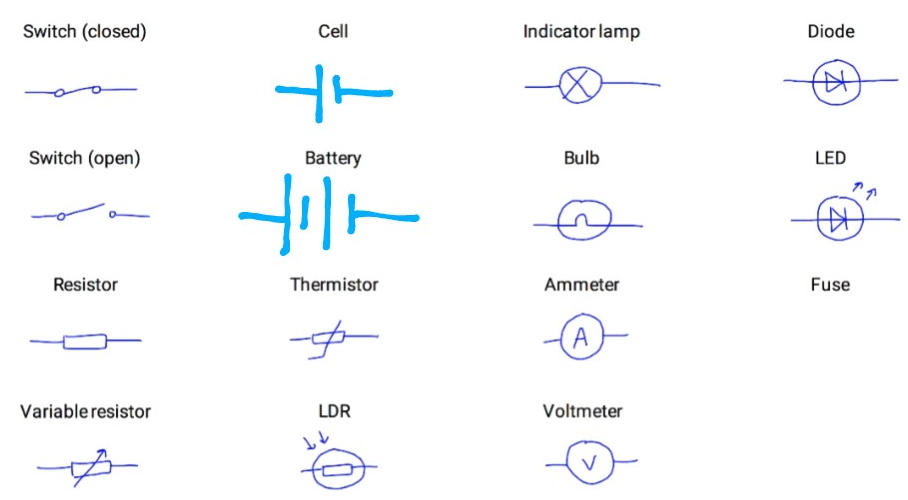
Fill in the gaps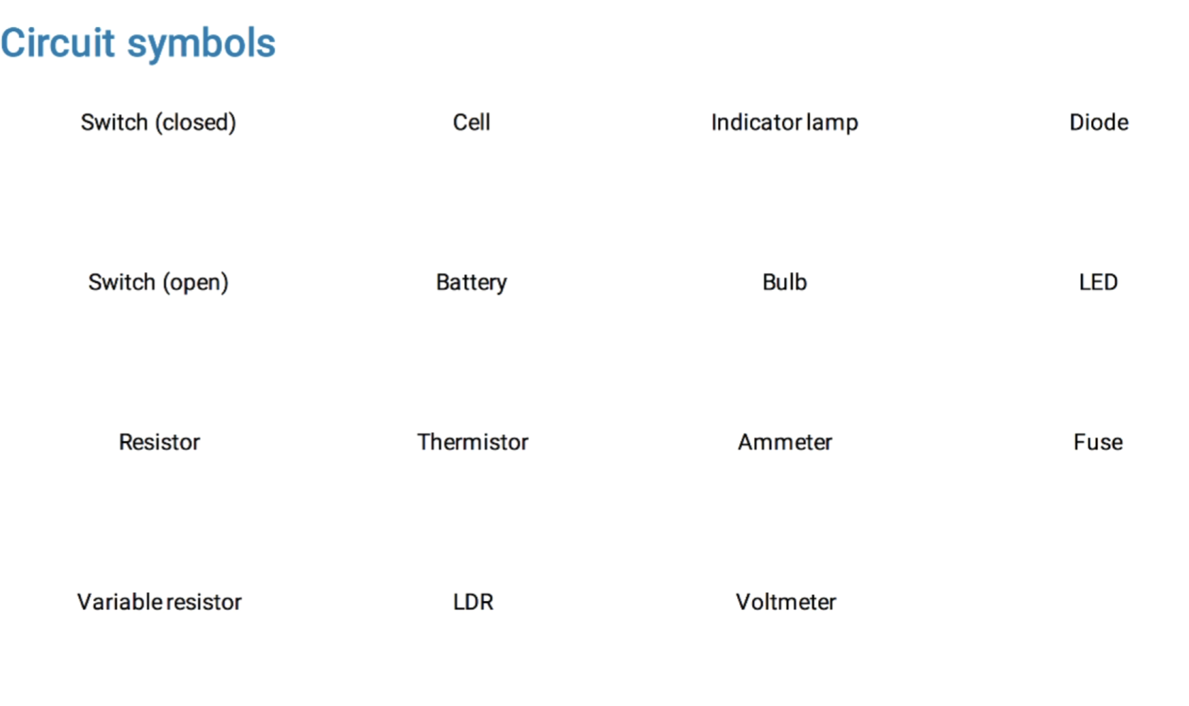
2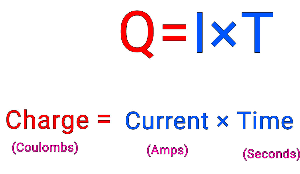
What is the formula for charge?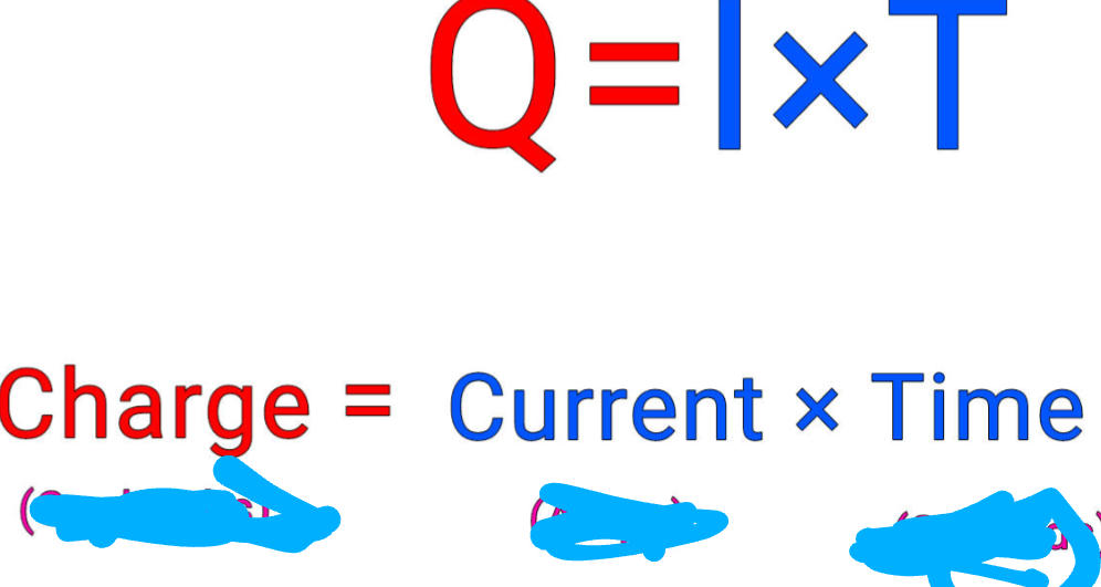
3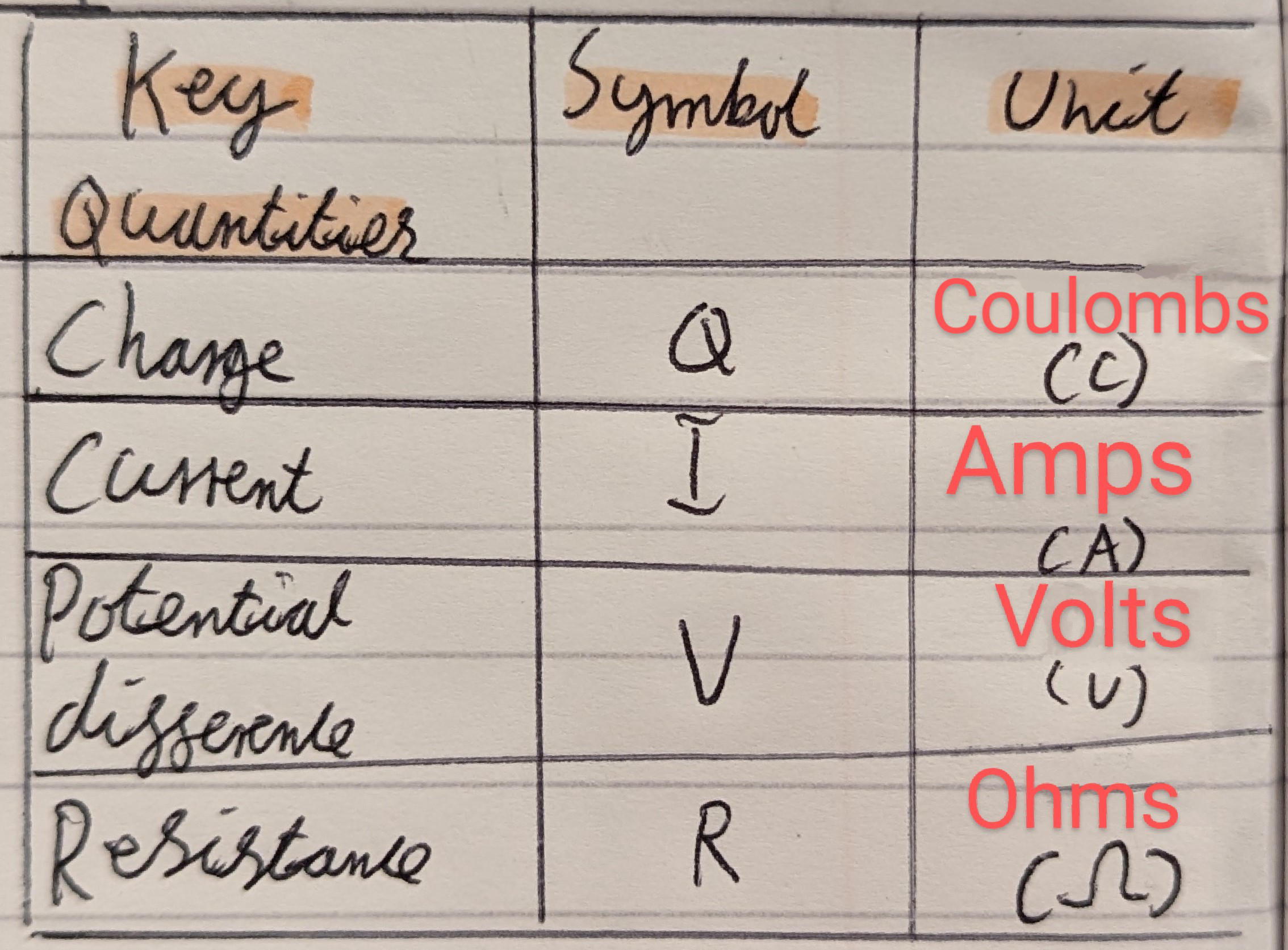
Fill in the table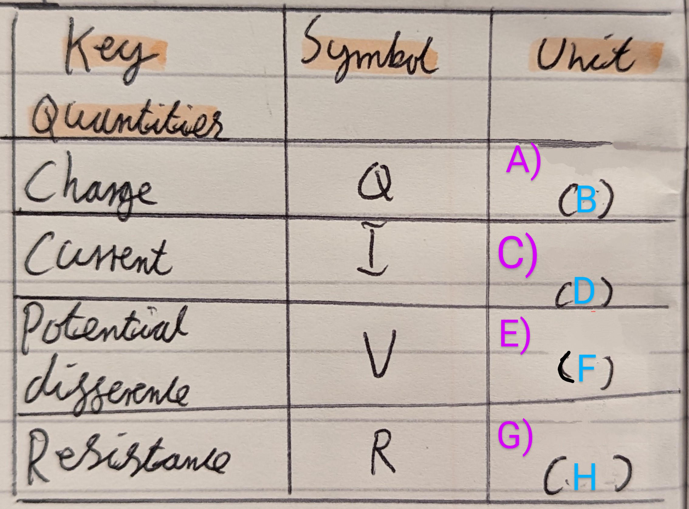
4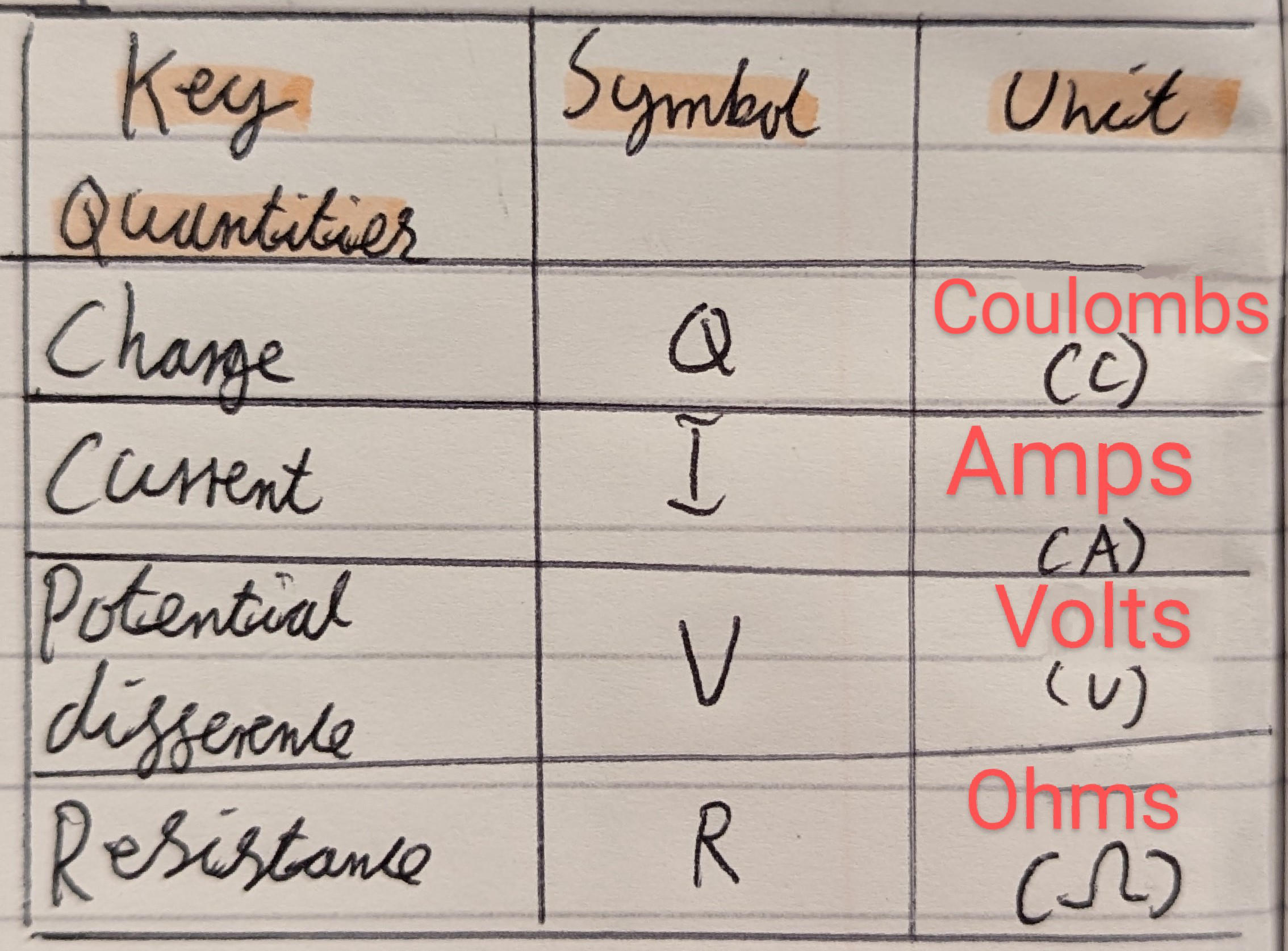
Fill in the gaps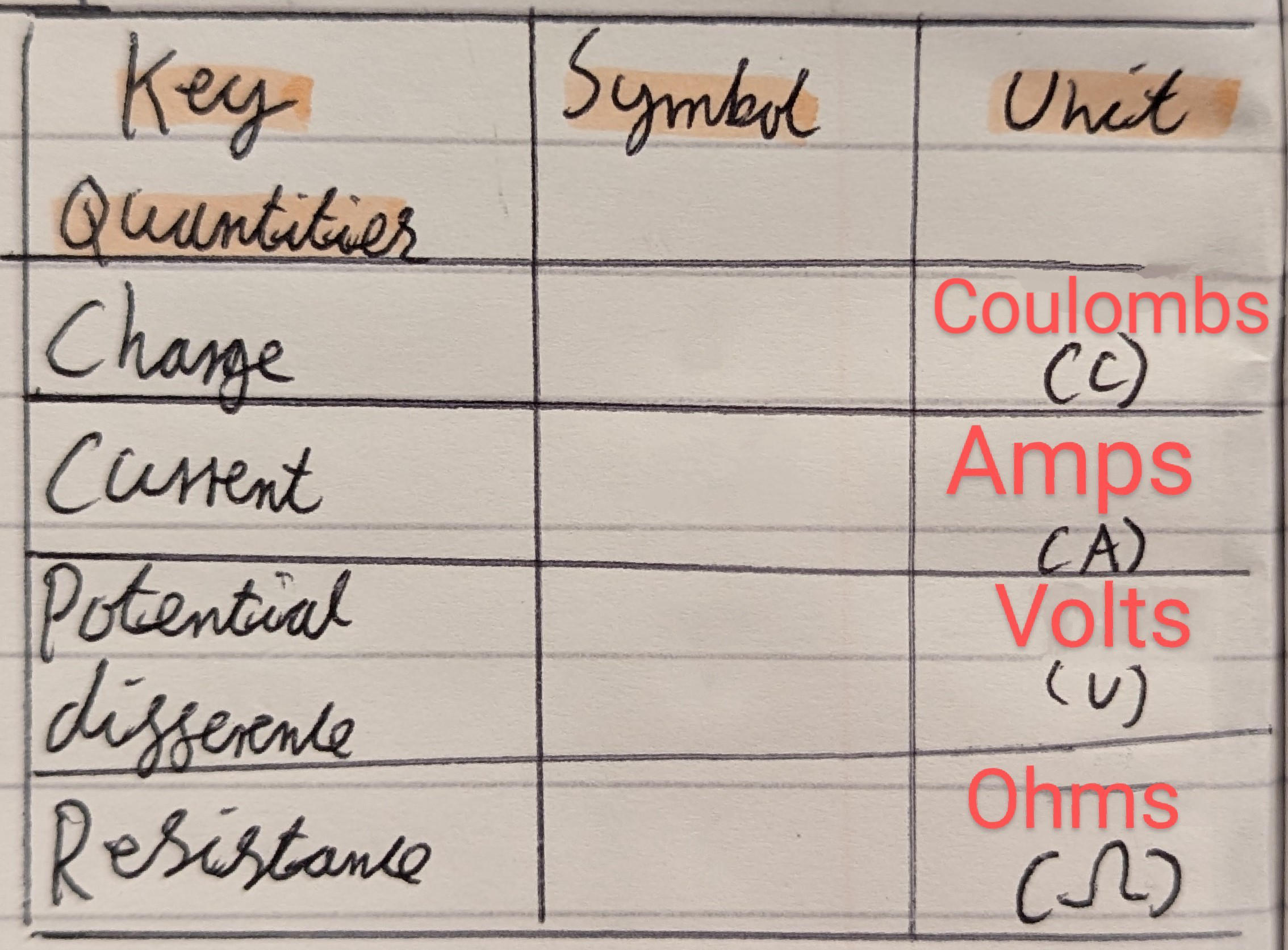
5
Define Diode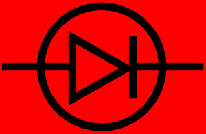
Allows Current To Flow One Direction Only.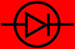
6
Define In Series & draw a series Circuit with Arrows Showing Where Current flows
One After Other.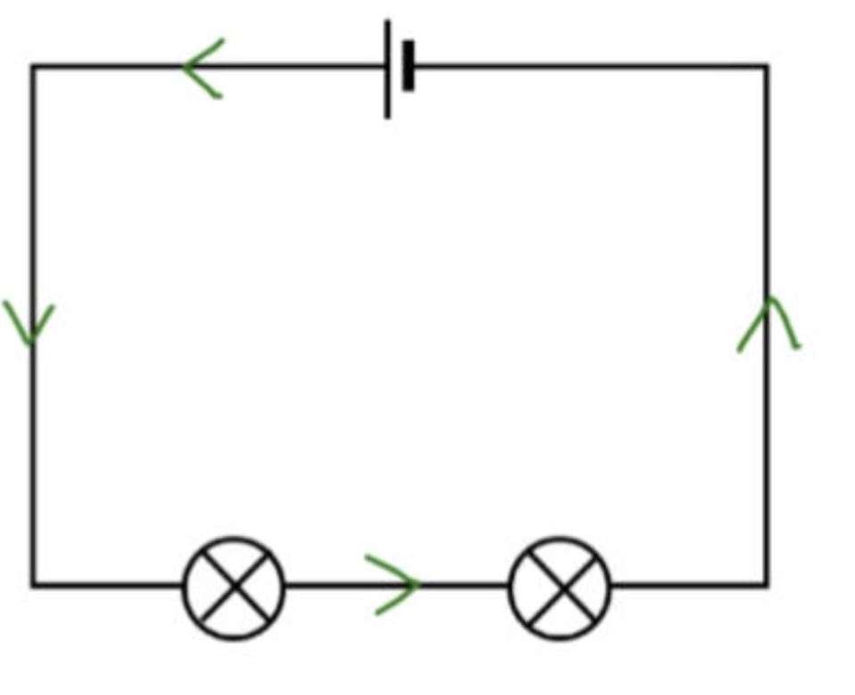
7
Define In Parallel & draw a Parallel Circuit with Arrows Showing Where Current flows
More Than One Path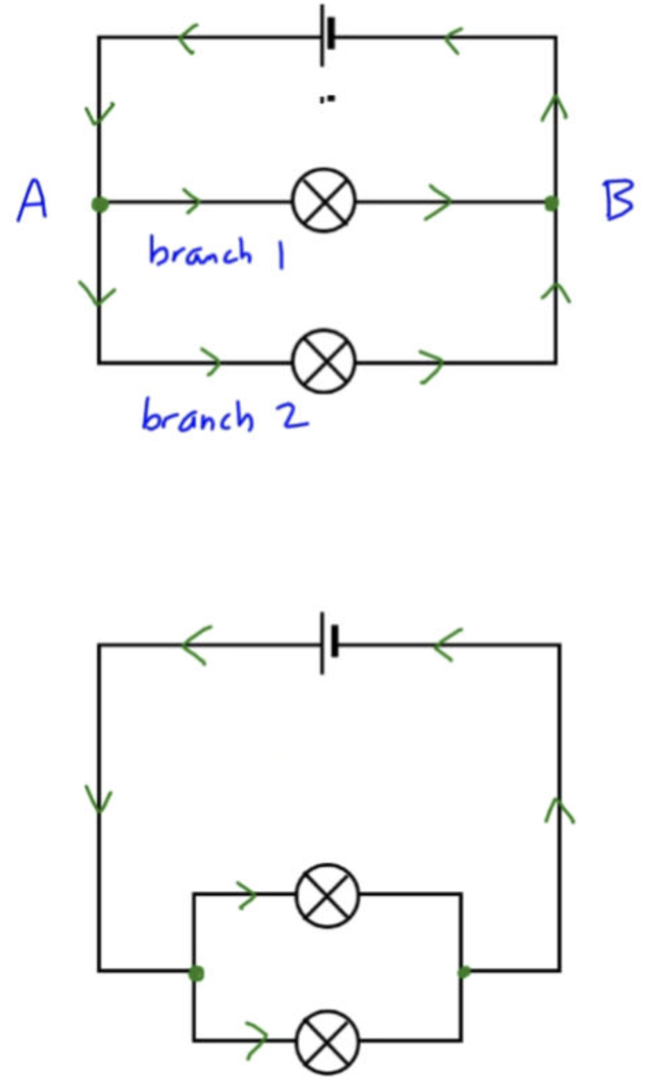
8
Define Cell
Pushes Current Round Circuit
9
What Measures Current & How is Placed in a Circuit?
Ammeter Connected in Series.
10
What Measures Voltage/Potential Difference & How is Placed in a Circuit?
Voltmeter Connected in Parallel.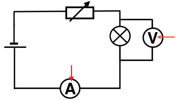
11
Define Current
Amount of Charge Flowing Past a Given Point Every Second
12
define electric current?
Amount Of Charge that Flows Per Second
Current= Charge÷time
Current= Charge÷time
13
define electrons
Electrons are Negatively Charged Particles and they Transfer Energy Through Wires as Electricity.
14
define Resistance
Slowing Down Of Current
15
Define Resistor
Anything Reduces Flow of Current in Circuit
16
Define Power
Rate at Which Energy is Transferred or (doing work).
17
What does Ohms Law State?
Current Through Components is Proportional to PD Across It (Provided it's Temperature Remains Constant)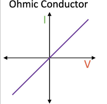
18
A Variable Resistor Is Set to a value of 5 ohms, and a current-voltage (I-V) graph
(with I on the y-axis and V on the x-axis) is plotted for it.
Its Resistance is then Doubled to 10 ohms. What effect will this have on its I-V graph?
(with I on the y-axis and V on the x-axis) is plotted for it.
Its Resistance is then Doubled to 10 ohms. What effect will this have on its I-V graph?
Resistance is Doubled So 'More Difficult' Current Get Through Component. Slope on I-V Graph DECREASE.
19
What are the two Non-Ohmic Conductors?
Filimant Bulb & Diode
20
What is the Component that Follows Oms Law?
Ohmic Conductor
21
Student wishes to Measure Resistance Of Filament Bulb. What Should They Do?
Voltmeters ALWAYS Connected in Parallel & Ammeters Series.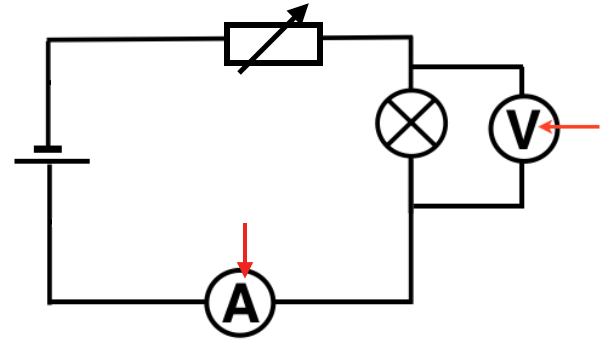
22
Define Non-ohmic
Non-ohmic conductors are conductors that do not follow ohm's law.
23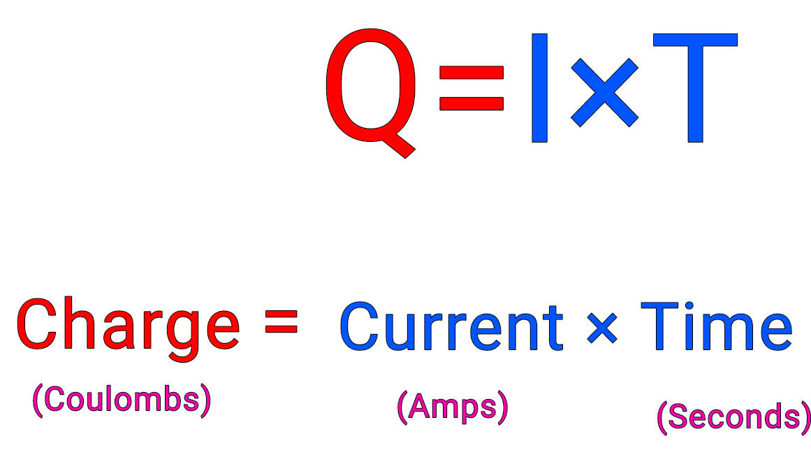
Charge Equation & Units 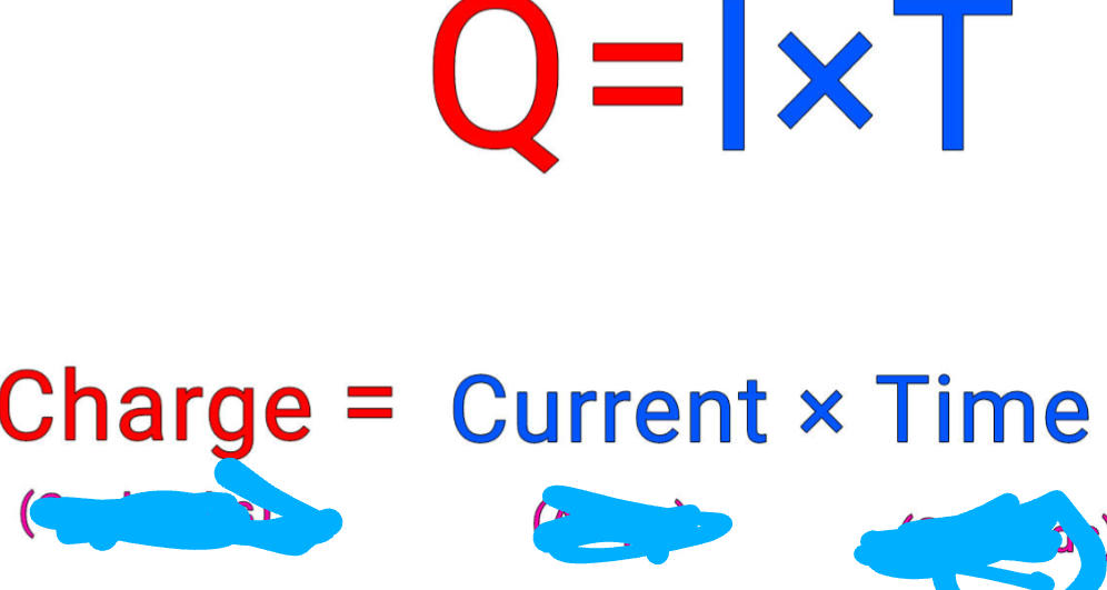
24
What does a Voltmeter measure?
voltmeter measures Potential Difference
25
where must a Voltmeter be placed in a circuit?
A Voltmeter must be connected in parallel with the component whose voltage you want to measure.
26
A current 1.5A through an electric toothbrush for 90 seconds. how much charge has flowed through the toothbrush?
Time×Current=Charge
90×1.5=135C/Coulombs
90×1.5=135C/Coulombs
27
how long would it take for 2000 Coulombs of charge to flow through a motor if the current is 2.5A?
Time×Current=Charge
X×2.5=2000
÷2.5 ÷2.5
2000÷2.5=X
X=800 Seconds
X×2.5=2000
÷2.5 ÷2.5
2000÷2.5=X
X=800 Seconds
28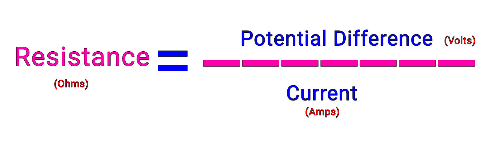
What is the formula for resistance?
29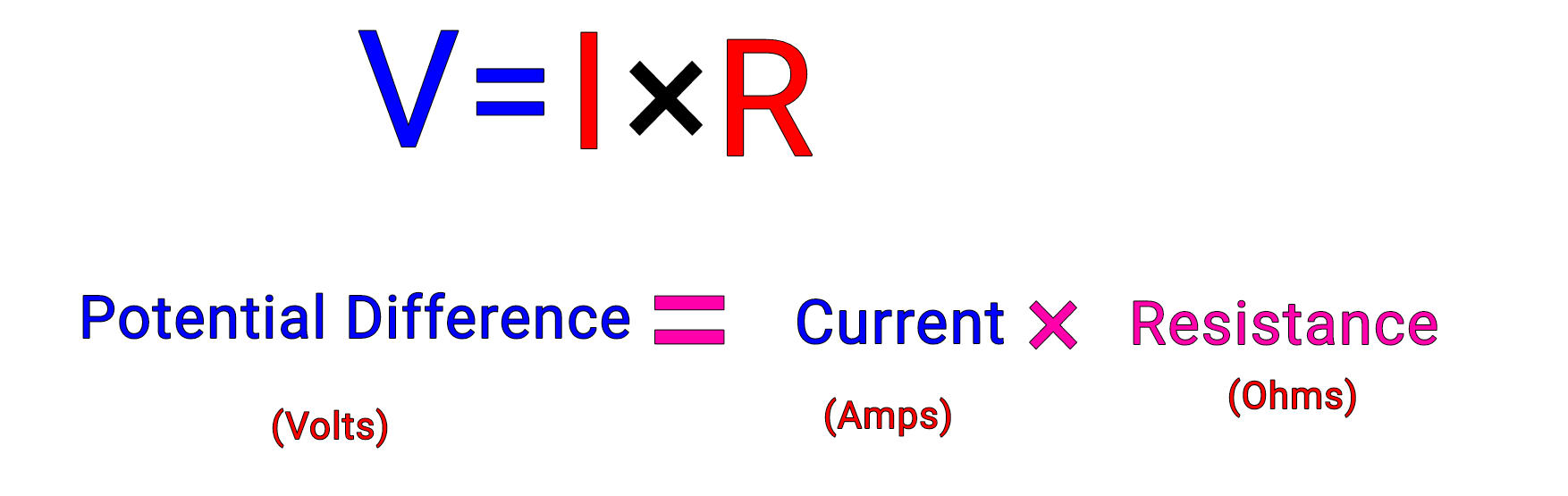
what is the formula for potential difference (Voltage)?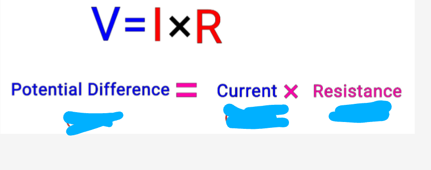
30
calculate the potential difference across a resistor when the current through it is 0.5 amps and the resistance of the resistor is 6 ohms.
0.5×6=3
31
calculate the current through a wire when the potential difference across it is 6 volts and the resistance is 3 ohms?
Resistance= Potential Difference ÷ Current
6÷3=2
6÷3=2
32
what increase resistance being thinner or thicker?
Thin
33
What does IV Characteristics Refer to?
Graph Shows How PD Flowing Across Component Changes as Current Through it Increased.
34
What is the Characteristic for a Linear Component?
Straight Line
35
What is the Characteristic for a Non-Linear Component?
Curved IV Characteristic.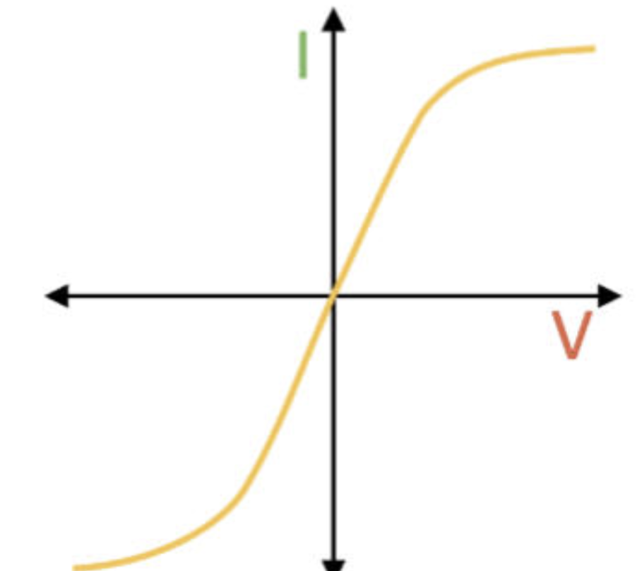
36
Describe I-V characteristics you get for an Ohmic Conductor & draw graph.
Current (I) Through Ohmic Conductor at Constant Temperature is Directly Proportional to PD (V). Get Straight Line.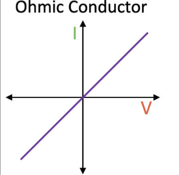
37
Describe I-V characteristics you get for an Filament Bulb & draw graph.
As Current (I) increases Temperature of Filament increases so Resistance increases. Meaning Less Current Flow Per Unit PD.
Graphs gets Shallower-Curve.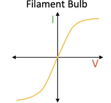
Graphs gets Shallower-Curve.
38
Describe I-V characteristics you get for an Diode & draw graph.
Current Flow in One Direction. Diode Strong Resistance in Opposite Direction.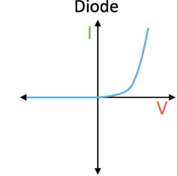
39
Define Potential Difference (voltage)
Measure of Energy, Per Unit Of Charge, Transferred Between Two Points In a Circuit
40
what increases resistance being short or long?
Long
41
what other factor needs to be considered that may increase resistance?
Material
42
what is electricity measured in?
Joules (J)
43
what were the Resistance Required Practical results ?
increase Length of Wire, Resistance of Wire Increases.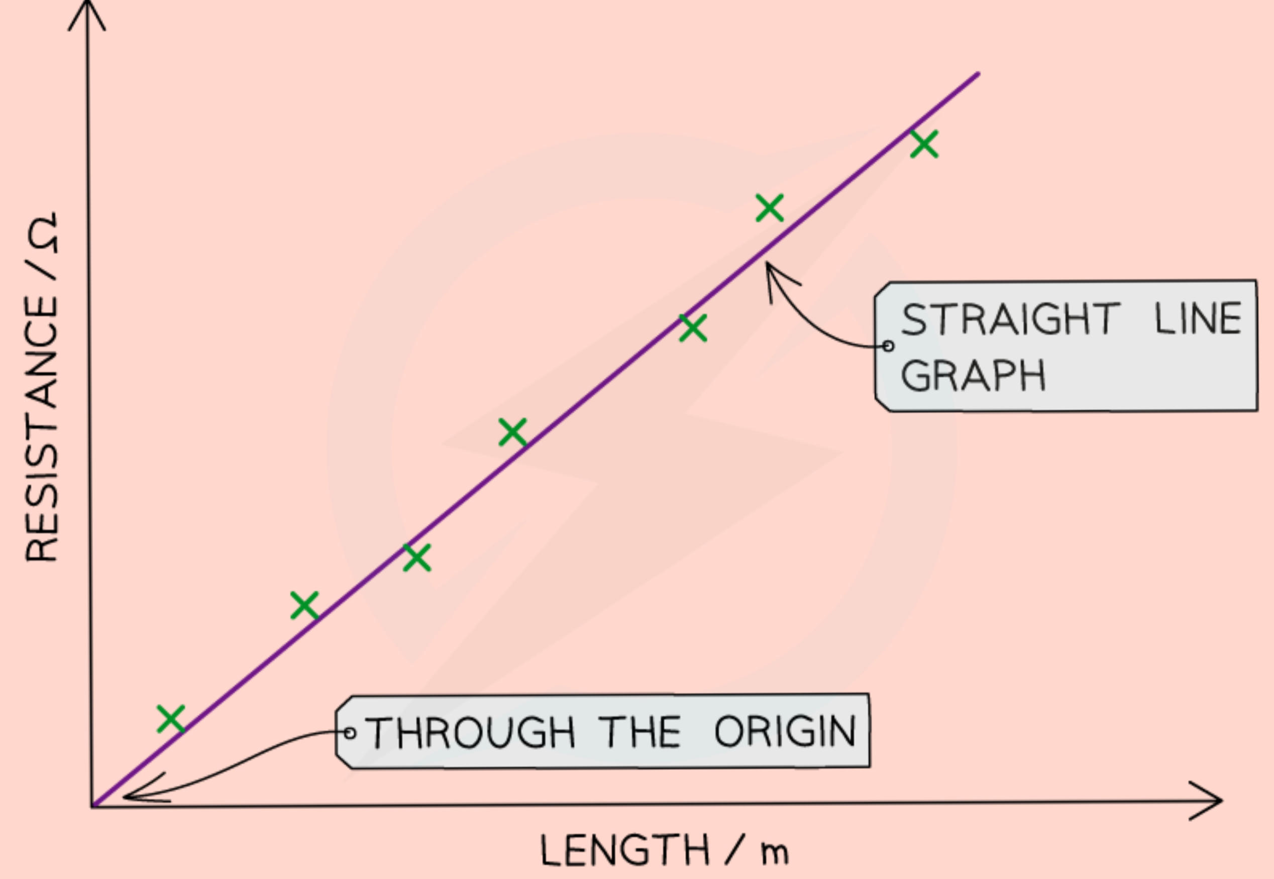
44
What was the independent & dependent variable for the Resistance REQUIRED PRACTICAL?
Independent Variable: Length Of Wire
Dependant Variable: Resistance
Control Variable:
Dependant Variable: Resistance
Control Variable:
45
Describe how you would obtain the data (method) for the Resistance REQUIRED PRACTICAL?
1) Connect 20cm Wire to Circuit Using Crocodile Clips
2) Measure P.D Across Wrire (V) & Current Through it (I)
3) Calculate Resistance of Wire (Use V=IR)
4) Repeat Step 2 & 3 for lengths 30-90 in Tens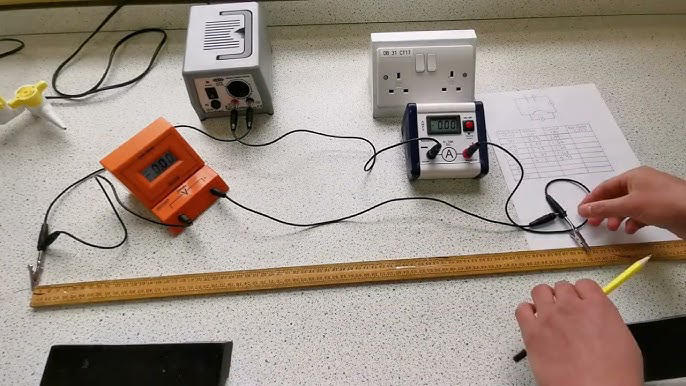
2) Measure P.D Across Wrire (V) & Current Through it (I)
3) Calculate Resistance of Wire (Use V=IR)
4) Repeat Step 2 & 3 for lengths 30-90 in Tens
46
What would cause a Resistance of a Piece of Wire Increase?
Increasing Length
47
When two resistors are connected in series, their total resistance is 100 ohms. What can be said about their total resistance when they are connected in parallel?
Less than 1000ohms
48
10 cm-long piece of wire has a resistance of 1.20 ohms Calculate the resistance of a 70 cm-long piece of wire which is made from the same material, has the same cross-sectional area and is at the same temperature?
10=1.2
1.2×7=8.4
70=8.4 ohms
1.2×7=8.4
70=8.4 ohms
49
What causes current and resistance?
• A potential difference causes the delocalised electrons to flow: this is called an Electrical Current.
• The more positive metal ions there are in the wire, the more the flow of the electrons are slowed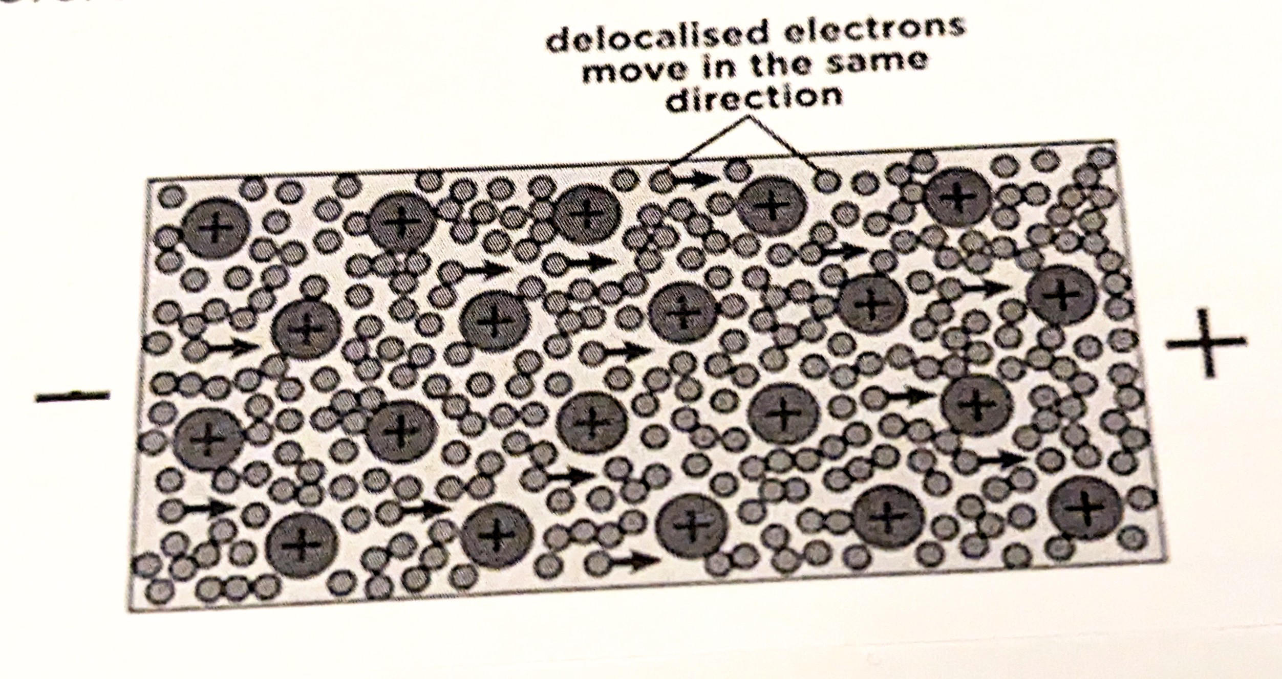
• The more positive metal ions there are in the wire, the more the flow of the electrons are slowed
50
What do opposite charges do?
Opposite charges attract
51
What do same charges do?
Same charges repel
52
What is Earthing and why do we do it?
The Charge Carries To the Ground.
We do this because Electrical Earthing is Done to get Protection from the Risk of Electrical Shock.
We do this because Electrical Earthing is Done to get Protection from the Risk of Electrical Shock.
53
When a Van de Graph Is Running, what is Produced?
Large Charge Develop On Dome.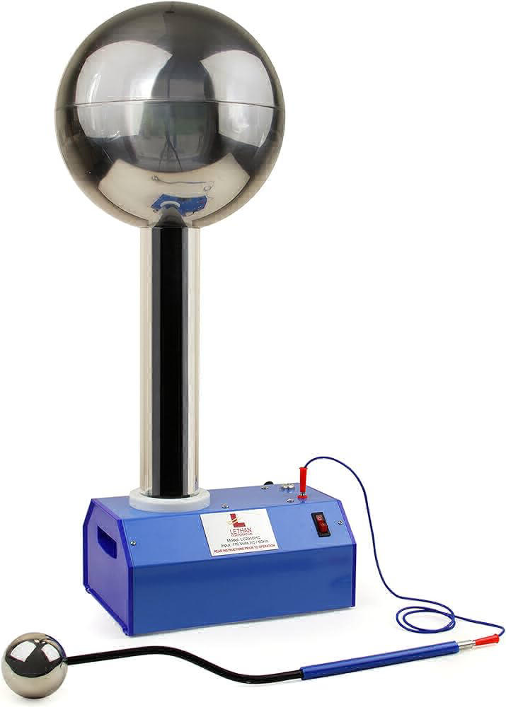
54
How do Static Charges Built Up on an Object?
• Electrostatic Forces
• Charging by Friction
• Charging by Friction
55
Define Conductor & Give Example
Allows Charge Flow Through Them Easily.
Metal.
Metal.
56
Define Insulator & Give Example
DO NOT Allow Charge Flow Through Them Easily.
Many Non-Metals.
Many Non-Metals.
57
What is an Electric Field?
Region in which Charged Particles will Experience Force
58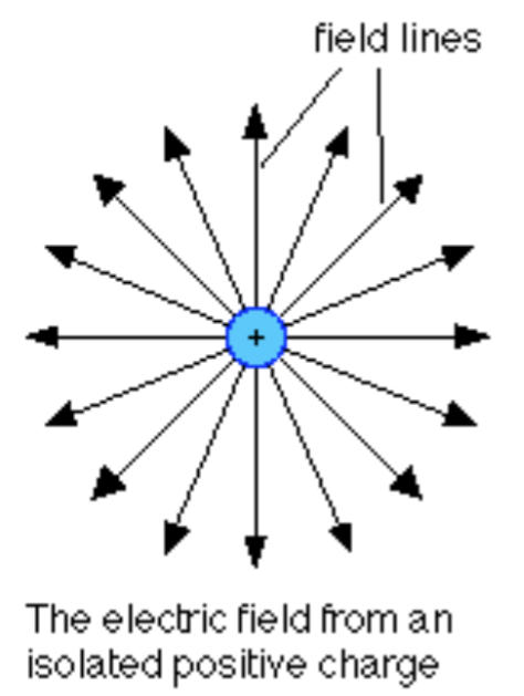
Draw a diagram for an Electric Field from an Isolated, Positive Charge.
59
what type of diagram is this?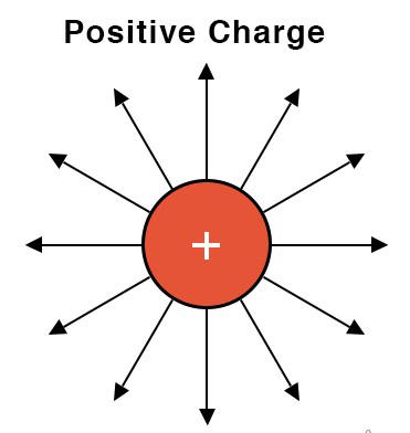
A diagram for an Electric Field from an Isolated, Positive Charge.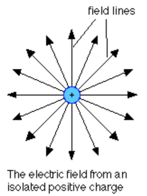
60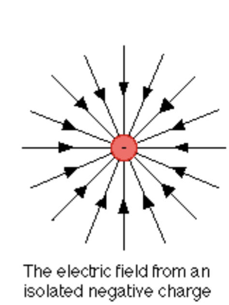
Draw a diagram for an Electric Field from an Isolated, Negative Charge.
61
what type of diagram is this?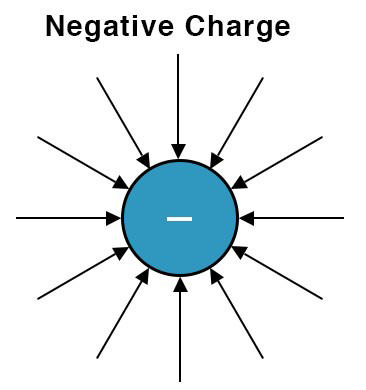
A diagram for an Electric Field from an Isolated, Negative Charge.
62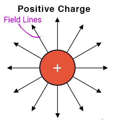
Label the Field Lines for the Electric Field Patterns Diagram
63
What do More Closely Spaced Field Lines Show?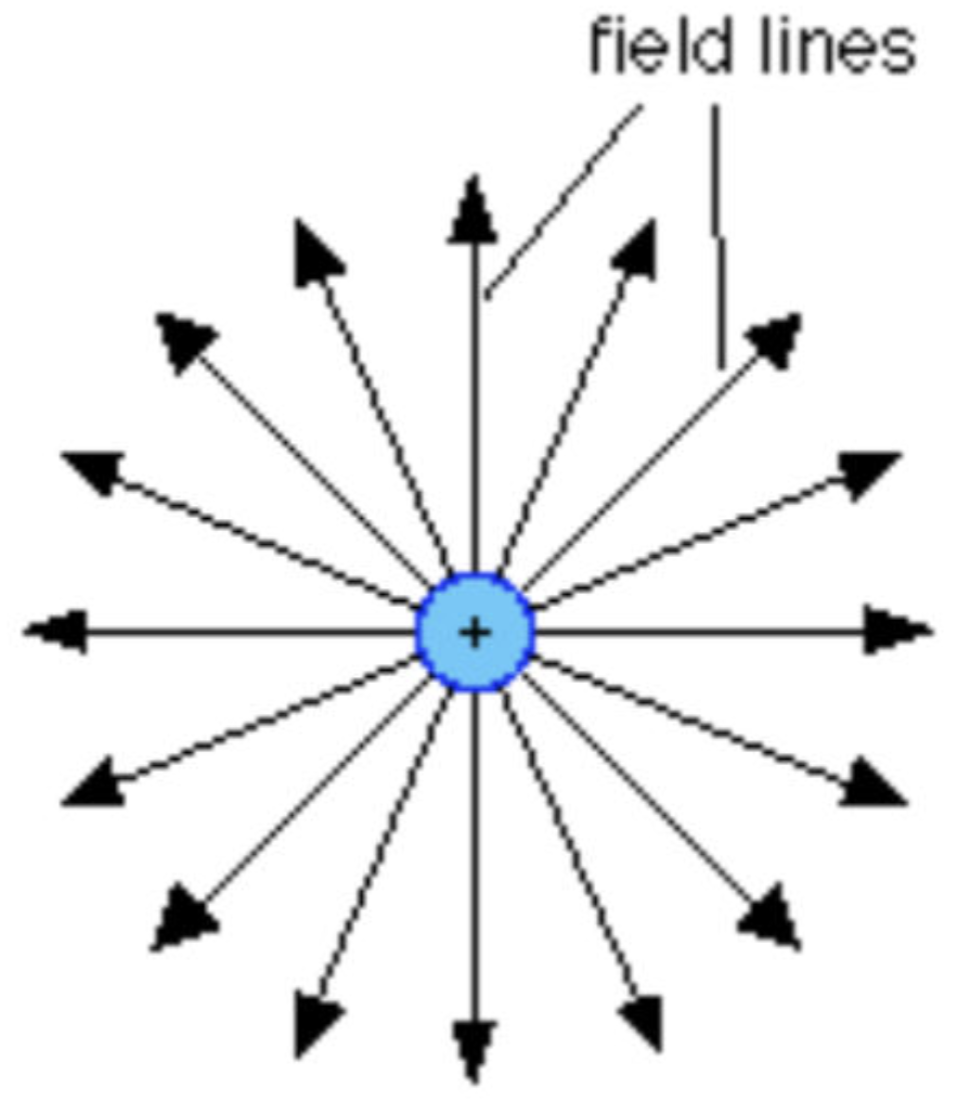
Stronger the Field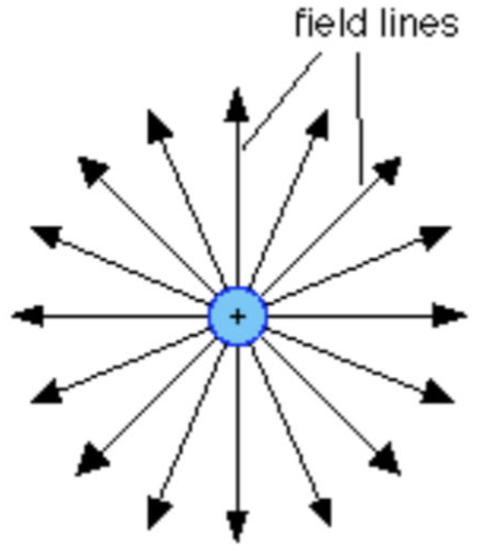
64
What Will Negative Charges Always Experience?
Negative Charges Will Always Experience Force Opposite To Direction Which Field Lines Pointing
65
What do Arrows Show in Electric Fields?
Direction of Force Which will be Exerted on Positive Charge in Field.
66
What happens when negative electrons are ripped off?
Electrons , which are Negatively Charged, may be 'ripped off' One Material and on to the Other.
The Material that Gains Electrons Becomes Negatively Charged.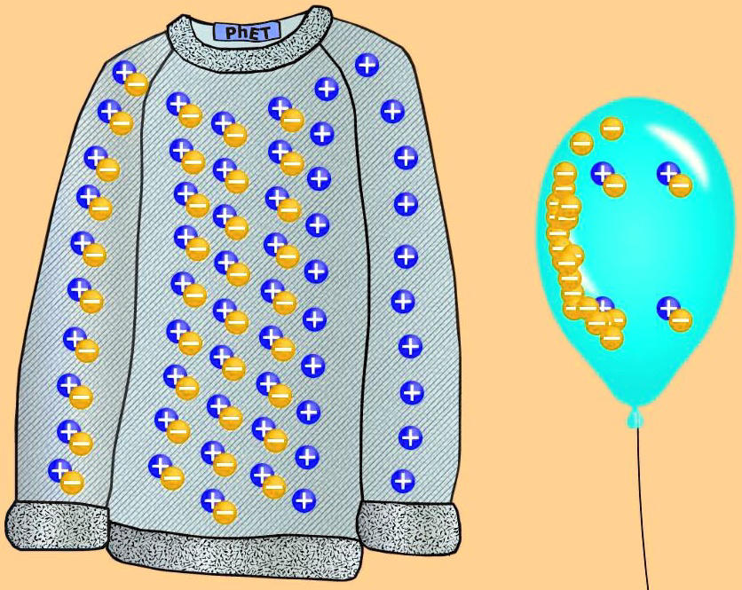
The Material that Gains Electrons Becomes Negatively Charged.
67
How do you work out the Resistance in a Series?
Total Resistance Is Sum Of Resistances of Each Component.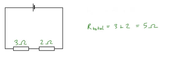
68
How do you work out the Resistance in a Parallel?
Total Resistance Is Less Than Resistance of Smallest Resistor.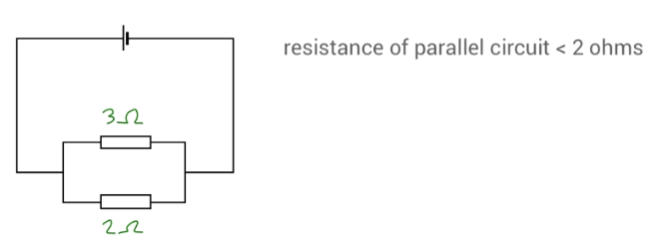
69
workout the total resistance of the bulbs for a series circuit?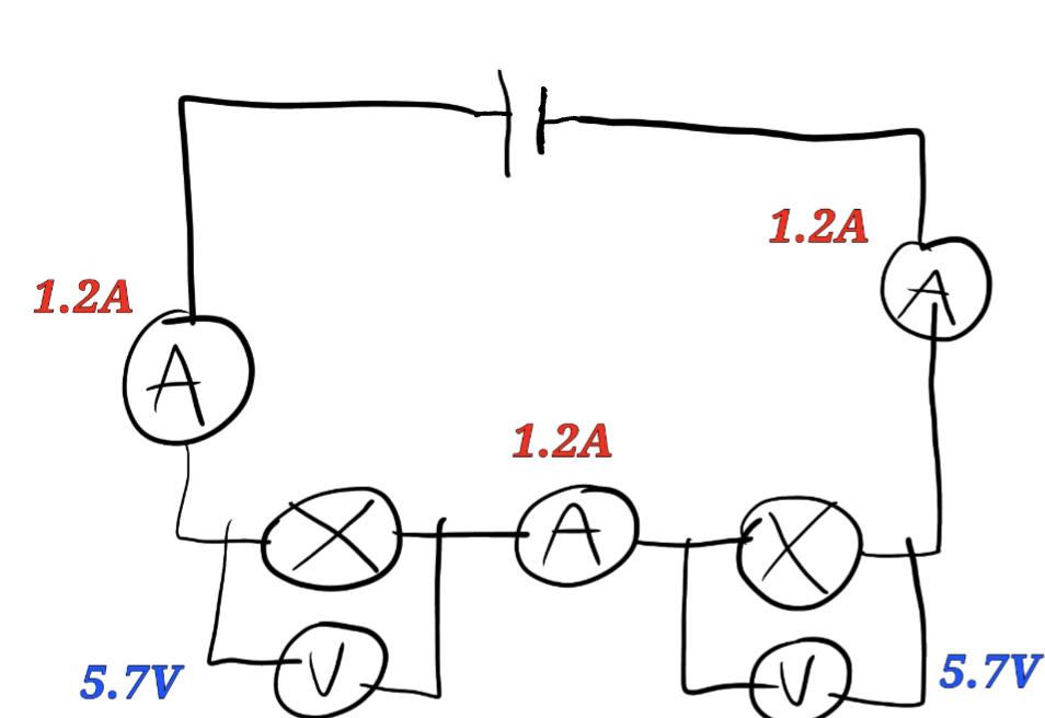
Resistance= Potential Difference ÷ Current
5.7÷ 1.2= 4.75 IS RESISTANCE FOR 1 BULB
So 4.75×2=9.5 is the TOTAL RESISTANCE
(2 bulbs)
5.7÷ 1.2= 4.75 IS RESISTANCE FOR 1 BULB
So 4.75×2=9.5 is the TOTAL RESISTANCE
(2 bulbs)
70
workout the total resistance of the bulbs for a parallel circuit?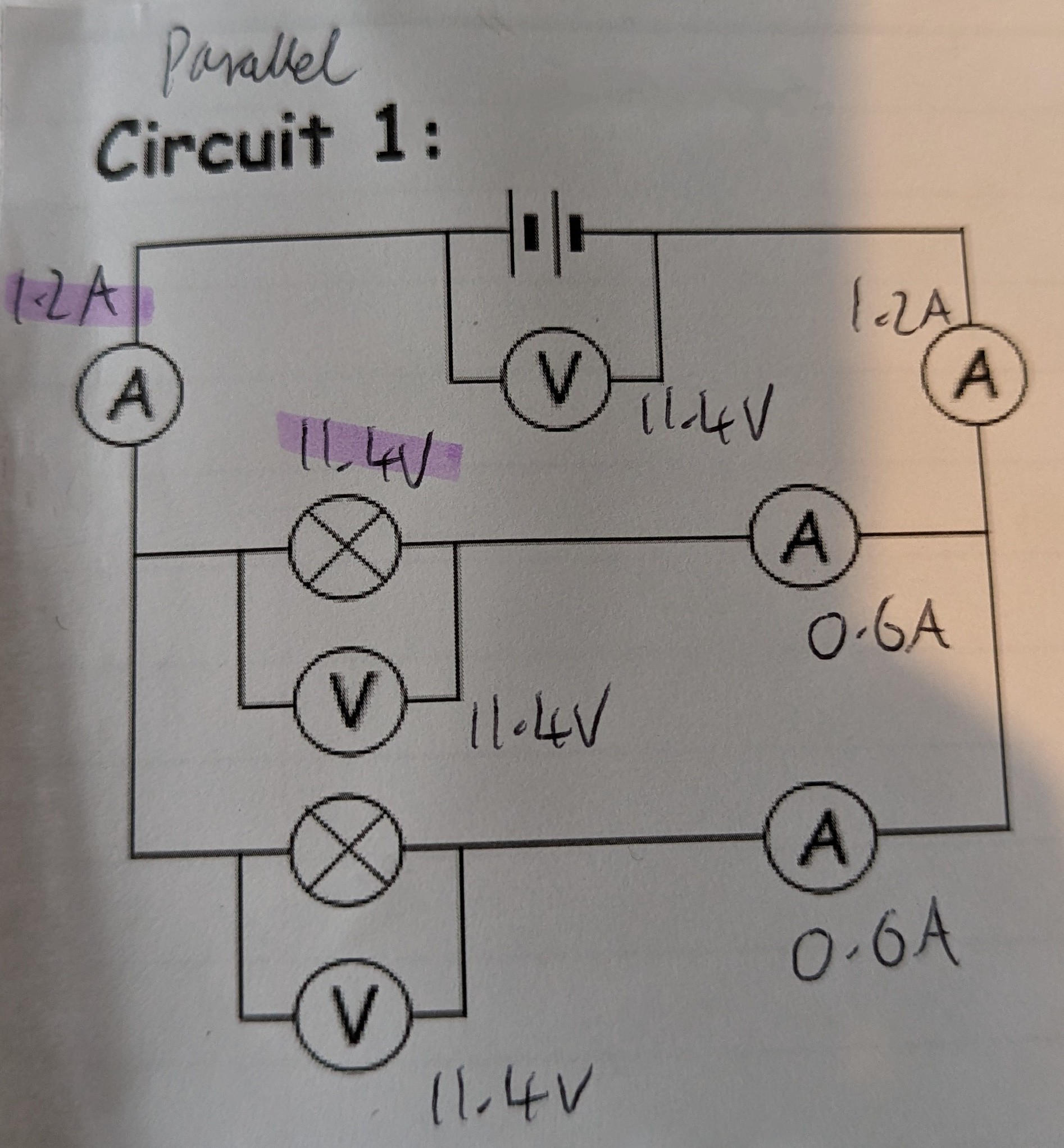
Resistance= Potential Difference ÷ Current
11.4V ÷ 1.2A= 9.5 Ohms
CAN ONLY DO THIS FOR PARALLEL CIRCUITS!!
Divide the amps and volts for the top bit before split. Remember the total resistance is always less than the smallest individual resistance.
e.g 1 bulb as more resistance than the total resistance
Total resistance= 9.5 Ohms
Resistance for 1 bulb= 19 Ohms (11.4÷0.6=19 Ohms)
11.4V ÷ 1.2A= 9.5 Ohms
CAN ONLY DO THIS FOR PARALLEL CIRCUITS!!
Divide the amps and volts for the top bit before split. Remember the total resistance is always less than the smallest individual resistance.
e.g 1 bulb as more resistance than the total resistance
Total resistance= 9.5 Ohms
Resistance for 1 bulb= 19 Ohms (11.4÷0.6=19 Ohms)
71
What type of circuit is this? 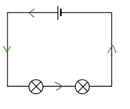
A Series Circuit
72
What type of circuit is this? 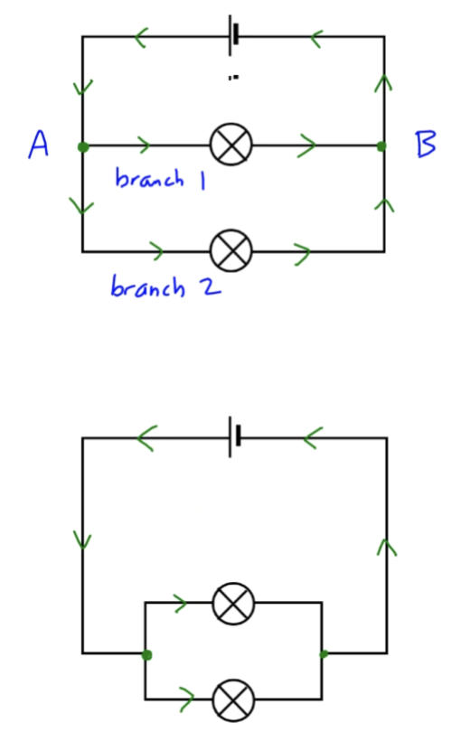
A Parallel Circuit.
73
how is Potential Difference affected by different circuits?
Series: Total PD of Power Supply Shares Between Components
Parallel: PD Across Each Component & Branch is Equal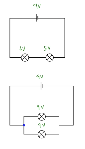
Parallel: PD Across Each Component & Branch is Equal
74
how is current affected by different circuits? 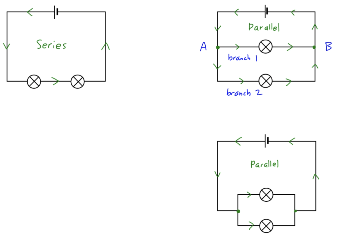
Series: Current is same everywhere.
Parallel: Sum Of Currents Through Each Path is Equal To Total Current That Flows From Source.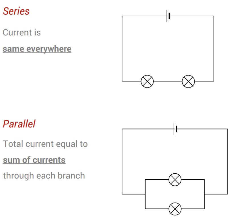
Parallel: Sum Of Currents Through Each Path is Equal To Total Current That Flows From Source.
75
how to work out the total resistance in a Parallel Circuit?
Divide the amps and volts for the top bit before split.
Remember the total resistance is always less than the smallest individual resistance.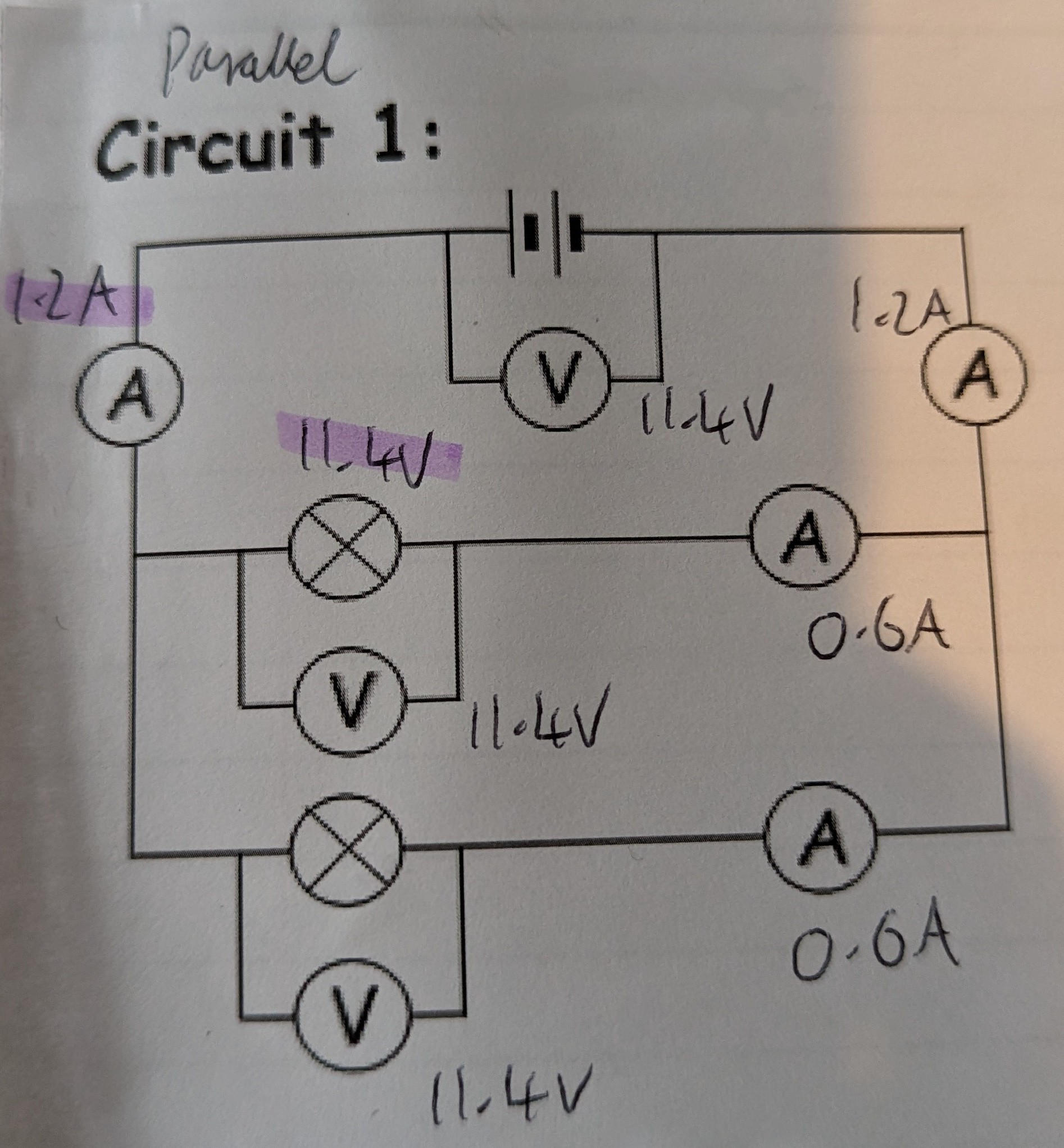
Remember the total resistance is always less than the smallest individual resistance.
76
Describe how resistance in a Thermistor varies with temperature and give examples of its use.
As the Temperature Increases the Resistance Decreases.
Thermistors are used as Temperature Sensors,
For examplethey are used in fire alarms.
Thermistors are used as Temperature Sensors,
For examplethey are used in fire alarms.
77
Describe how resistance in a LDR varies with Light Intensity and give examples of its use.
As the Light intensity Increases the Resistance Decreases.
LDRs (light-dependent resistors) are used to detect light intensity,
For example they are used in automatic security lights.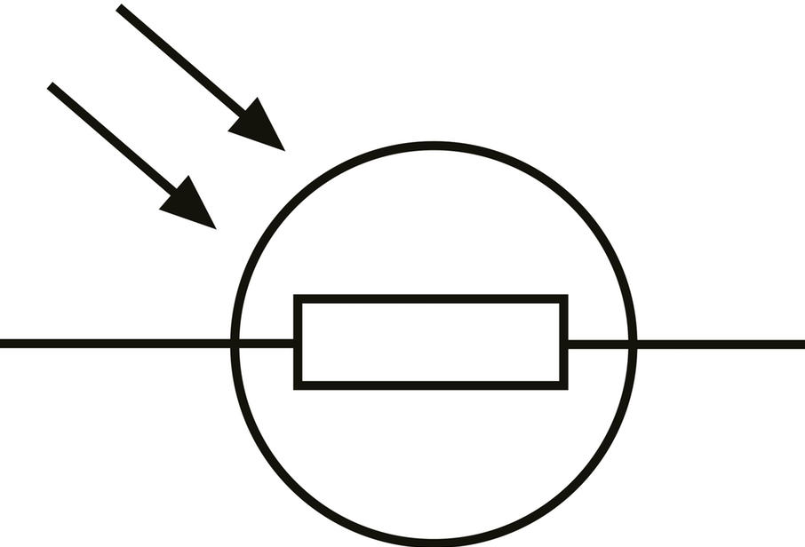
LDRs (light-dependent resistors) are used to detect light intensity,
For example they are used in automatic security lights.
78
describe and explain how resistance of a Parallel Circuit changes with adding more resistors?
Adding more resistors in a Parallel Circuit:
• Decreases Total Resistance
• Increases Total Current
• Potential Difference stays the Same Across Each Resistor.
• Decreases Total Resistance
• Increases Total Current
• Potential Difference stays the Same Across Each Resistor.
79
How to work out Resistance of component?
Measure Current Through & P.D Across Component
V=IR
V=IR