HVAC PE Study
Study these flashcardsFree · spaced repetition · iPhone, Android, Mac & web
All cards
1
oz to lb
16 oz = 1 lb
2
Hz to RPM
1 Hz = 60 RPM
3
Rad/s to Hz
1 rad/s / 2pi = 1 Hz
4
Equivalent Thickness
$t_{eq}=r_{2}ln(\frac{r_{2}}{r_{1}})$
5
Energy Utilization Index (EUI)
${total~yearly~energy}/{building~area}$
6
Cost Utilization Index (CUI)
${total~yearly~energy~cost}/{building~area}$
7
Calculate Rate of Return
Equate two figures into the same time period (e.g. annual) and solve for interest rate by looking up value on interest tables
8
Effect of building orientation on heat gain
Northern hemisphere:
south-facing: receive more sunlight in the winter
west-facing: receive more sunlight in afternoon during summer;
east-facing: receive more morning sunlight;
north facing: receive minimal sunlight year-round
south-facing: receive more sunlight in the winter
west-facing: receive more sunlight in afternoon during summer;
east-facing: receive more morning sunlight;
north facing: receive minimal sunlight year-round
9
Mechanical horsepower (MHP)
power produced by pump/fan; amount of power required to meet needs of the system
10
Brake horsepower (BHP)
power output of motor to turn on pump or fan; $BHP=\frac{MHP}{\eta_{mech}\%}$
11
(Standard) motor horsepower
size of the motor
12
Motor HP rating
standard size above BHP
13
Electrical Power (P)
electrical input required to turn on the motor and overcome friction losses
14
Real Power
Electricity that can do actual work
15
Power Factor
Used to find real power; $S_{supplied~to~motor~(VA)}=\frac{P~[W]}{pf}$
16
Electrical horsepower efficiency
$\frac{Brake~HP}{\eta_{motor}\%}=\frac{{Mechanical~HP}}{\eta_{motor}\%*\eta_{mech}\%}$
17
Explain the vapor compression cycle
1. Evaporator: low pressure, low temp liquid/vapor mixture → absorbs heat → low pressure, high temp gas; 2. Compressor: low pressure, high temp gas → compressed high pressure, high temp gas; 3. Condenser: high pressure, high temp gas → high pressure, low temp liquid; 4: Expansion device: high pressure, low temp liquid → low pressure, low temp liquid/vapor mixture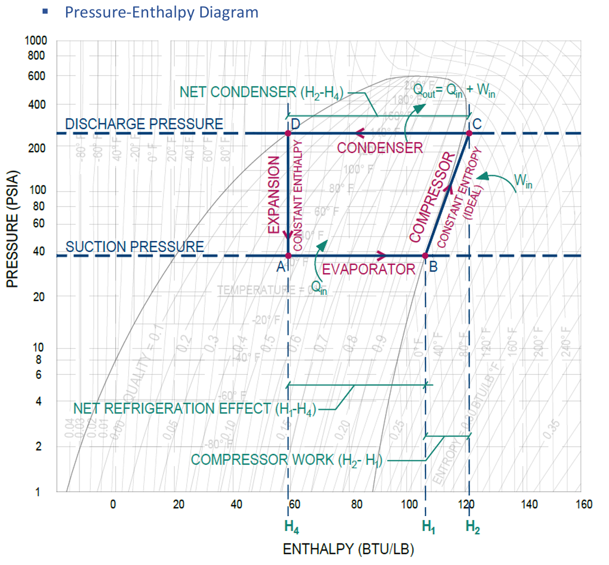
18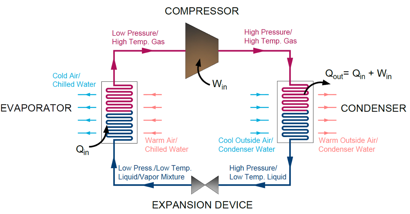
Vapor compression cycle steps
19
Evaporator
warm air/water used to evaporate all liquid parts of mixture into saturated vapor; isobaric and ideally isothermal; cool water to chilled water that is distributed to air handlers
20
Compressor
raises temperature of gas above temperature of fluid in condenser; ideally isentropic but some enthalpy change due to not being 100% efficient
21
(Isentropic) Compressor efficiency
$Compresser~Efficiency~(\%)=\frac{h_{2,ideal}-h_{1}}{h_{2,actual}-h_{1}}$
22
Condenser
cold air.water used to remove heat from gas and condense it to liquid; reject heat to a heat sink via air cooling (fans blow air over condenser) or water cooling (piping to cooling tower)
23
Superheat
X degrees beyond the saturation temperature. Evaporator superheats gaseous refrigerant.
24
Expansion device
reduces pressure of liquid adiabatically, where some is turned to gas
25
EER
Energy efficiency ratio, measures practical efficiency of cycle; $EER=3.412*COP$
26
IPLV
Integrated part load value; kW/ton metric given at various % load at standard AHRI conditions
27
NPLV
Non-standard part load value; same as IPLV but adjusted to account for design (non-standard) conditions
28
Absorption cycle
two shells, refrigerant (water) + absorber (lithium-bromide/ammonia), heat source (hot water/steam, typically used with waste heat)
29
Absorption cycle COP
COP=evaporator energy (Btuh)/Heat in (Btuh), typically 1.5
30
Isentropic
constant entropy; ideal compressors
31
Adiabatic
constant enthalpy; heat does not enter/leave system; dehumidifiers, evaporative coolers, expansion valves, throttling valve
32
Isothermal
constant temperature
33
Isobaric
constant pressure
34
Generic steam, refrigerant, and total heat equation
$Q=\dot{m}\Delta h$ or $q=mC_{p}\Delta T$
35
Sensible heat ratio
$SHR=\frac{{Sensible~Heat}}{Total~Heat}$, i.e. slope of line on the protractor
36
Heat of vaporization
$h_{gf}=h_{g}-h_{f}$; energy to vaporize liquid to gas
37
Lever rule
$T_{mix,db}=T_{1,db}*\%_{1}+T_{2,db}*\%_{2}=\frac{{T_{1,db}*CFM_{1}+T_{2,db}*CFM_{2}}}{CFM_{1}+CFM_{2}}$
38
What is the lever rule valid for?
Dry bulb temperature, humidity ratio, or enthalpy. NOT wet bulb temperature
39
Dew point
Horizontally left from point until you hit saturation curve. NOT the same as wet bulb temperature.
40
Horizontally right on psychrometric chart
sensible heating, decrease in RH; heating coils
41
Horizontally left on psychrometric chart
sensible cooling, increase in RH; cooling coils
42
Vertically up on psychrometric chart
latent heating, humidification; steam humidifier
43
Vertically down on psychrometric chart
latent cooling, dehumidification
44
Energy added from steam humidification
Use the slope obtained from the nomograph on the psych chart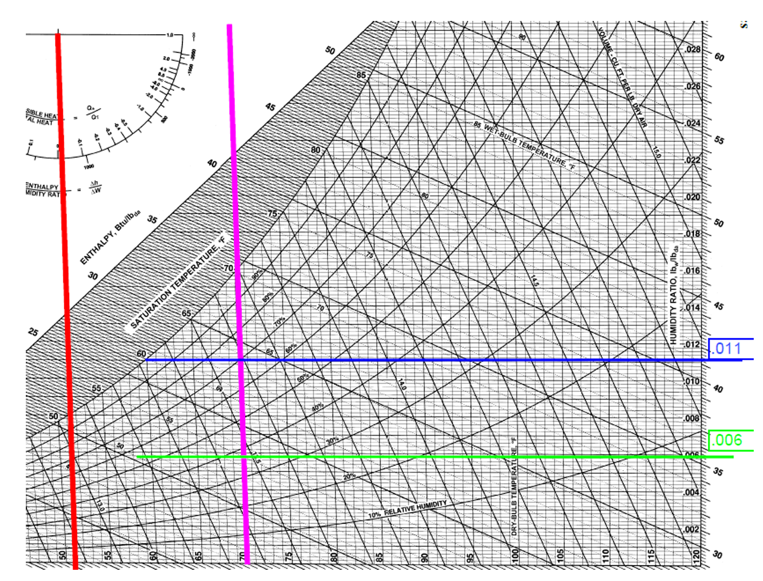
45
Chemical dehumidifier
downward diagonal movement depending on temperature of desiccant; possibly adiabatic
46
Regeneration
Heating dessicant to retransfer moisture into air
47
Lithium-Chloride
Can be sprayed with water solution over humid air to dehumidify; Li-Cl has high affinity for water
a) higher concentration of Li-Cl absorbs more moisture and vice versa
b) lower temperature can absorb more moisture and vice versa
a) higher concentration of Li-Cl absorbs more moisture and vice versa
b) lower temperature can absorb more moisture and vice versa
48
Evaporative cooling
Blow dry air over water or through water droplets
upward diagonal to left; essentially adiabatic since enthalpy lost be sensible cooling is gained by latent heating
upward diagonal to left; essentially adiabatic since enthalpy lost be sensible cooling is gained by latent heating
49
Altitude correction equation
in the handbook. only use DF or corrected air density, not both.
50
Heat from steamflow
$Q_{steam}=\dot{m}*h_{fg}$
51
Conductive heat transfer coefficient k units
per thickness, can be per inch $[\frac{Btu-in}{{hr*ft^2*^\circ}F}]$ or per ft $[\frac{Btu}{{hr*ft*^\circ}F}]$
52
Resistance to heat transfer
the reciprocal of conductive heat transfer coefficient, k (includes thickness); $\frac{{hr*ft^2}*^{\circ}F}{Btu*in}$
53
Resistance in series
sum of all resistances
54
Resistance in parallel
reciprocal of all resistances summed
55
Convective heat transfer coefficient
h, based on flow over surface; check handbook of h value of vertical, horizontal surfaces with/without wind
56
Black body
most efficient at emitting radiation and absorbing incident energy; emissivity = absorptivity = 1
57
$\alpha + \rho + \tau$
always equal to 1 for any type of body
58
Identify heat gains and their forms of heat transfer
roof/walls: conduction/solar radiation
skylights/windows: conduction/solar radiation
ventilation/infiltration
lights
people
equipment
skylights/windows: conduction/solar radiation
ventilation/infiltration
lights
people
equipment
59
Heating load sources
roofs/walls: conduction
skylights/windows: conduction
ventilation/infiltration
skylights/windows: conduction
ventilation/infiltration
60
Surface film coefficient
combined convective and radiative heat transfer coefficient for indoor and outdoor conditions to help find overall heat transfer coefficient; values in the handbook
61
CLTD
Cooling Load Temperature Difference; used for heat transfer through roof and walls instead of change in temperature
Only used for cooling loads
Only used for cooling loads
62
Heat gain from motors
depends on how the motor is configured relative to its respective equipment; equations in handbook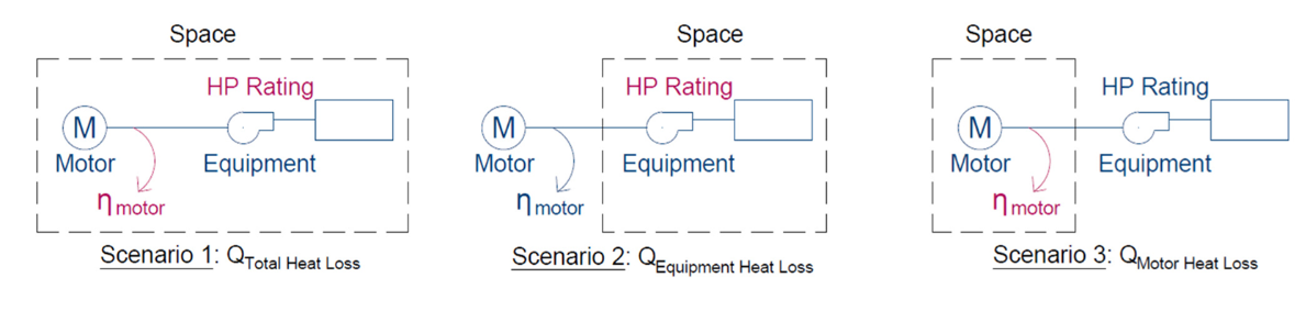
63
Appliances/Kitchen equipment heat transfer
hooded appliances have only sensible heat load since all latent and convective loads removed; if hooded use radiation factor
64
Surface temperature of pipes
$Convection~(T_{inside}-T_{surface})=Conduction~(T_{surface}-T_{ambient})$
65
Apparatus dew point (ADP)
temperature at which all air would be cooled if the cooling coil was 100% effective. Must be on saturation curve
66
Contact factor
how much of air hits and is cooled by coil, percentage of air cooled to apparatus dew point; $Contact~factor=1-Bypass~Factor$
67
Bypass factor
percent of air not cooled to ADP, function of airflow; $Bypass~Factor=\frac{{h_{leaving~coil}-h_{ADP}}}{h_{entering~coil}-h_{ADP}}=\frac{{T_{leaving~coil}-T_{ADP}}}{T_{entering~coil}-T_{ADP}}=\frac{{W_{leaving~coil}-W_{ADP}}}{W_{entering~coil}-W_{ADP}}$
68
Fitting losses
account for fitting losses using k as a loss factor (found in handbook)
69
Steam quality
$x=\frac{{h-h_{f}}}{h_{g}-h_{f}}=\frac{m_{vapor}}{m_{vapor}+m_{liquid}}$ (in handbook)
70
Explain how a cooling tower works
Transfers heat from water to air via evaporative cooling (via a small portion of liquid being evaporated by an airstream) to cool water. Air enters dry and leaves higher in temperature and near saturation while water is cooled down to a lower dry bulb temperature.; $q_{cold~water}=q_{air}$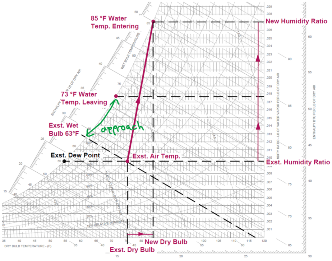
71
Approach
$Approach=T_{water,out}-T_{air,in,wb}$; describes performance of cooling tower, where the smaller the approach the closer to maximum possible heat transfer
72
Range
$Range=T_{water,in}-T_{water,out}$;
73
Effectiveness of cooling towers
$Effectiveness=\frac{Range}{Range+Approach}*100\%$
74
Water loss and make-up of cooling tower
Equate water heat loss to heat gain through evaporation: $500*Q~[gpm]~*(T_{in}-T_{out})=500*evaporation~rate~\left[ \frac{gal}{min} \right]*H_{vp}~\left[ \frac{Btu}{lbm} \right]$
75
Cooling tower - Drift
Amount of water carried out through airstream (~0.2%)
76
Blow-down
Draining of concentrated TDS then replacement with fresh water
77
Mechanical Cooling Tower
move air through cooling tower using mechanical fans
78
Natural draft cooling tower
move air based on difference in buoyancy of airstream inside and outside of cooling tower
79
Induced cooling tower
fans located at exit of airstream and suck air into cooling tower
80
Forced draft cooling tower
Fans blow into the cooling tower and located at airstream entrance
81
Counter-flow v Cross-flow
Counter-flow - air and water have directly opposing directions; cross-flow - air and water flow 90 degrees to each other
82
Higher heating value
gross heat from combustion of fuel (Btu/lb or Btu/lb^3)
83
Lower heating value
net heating value from combustion without latent heat of vaporization
84
Energy from a boiler/furnace
$Q_{boiler}=\dot{m}_{fuel}*{HHV}*\eta_{boiler}$
85
Condensing boiler
Extract additional heat from flue gases to provide higher efficiencies by condensing moisture out of waste stream to provide additional heating
86
Firetube boiler
non-condensing; products of combustion contained within boiler tubes and water passed over tubes within a shell
87
Watertube boiler
non-condensing; products of combustion within shell and water kept within small tubes
88
Parallel vs Counterflow heat exchanger
Counterflow increases coil capacity and maximizes heat transfer
89
NTU Method
Number of transfer units method; used for when LMTD unkown:
1. calculate NTU
2. Find effectiveness based on NTU and heat capacity ratio $C_{r}$,
3. Calculate heat transfer rate: $Q_{actual}=Q_{max}*\epsilon$, $Q_{max}=C_{min}*(T_{hot,in}-T_{cold,in})$
4. Solve for remaining unknowns using $Q=mc_{p}\Delta T$
1. calculate NTU
2. Find effectiveness based on NTU and heat capacity ratio $C_{r}$,
3. Calculate heat transfer rate: $Q_{actual}=Q_{max}*\epsilon$, $Q_{max}=C_{min}*(T_{hot,in}-T_{cold,in})$
4. Solve for remaining unknowns using $Q=mc_{p}\Delta T$
90
Absorption chiller
compressor is replaced with a generator/absorber and a heat source
91
Chiller (compressor) types
Positive displacement:
Scroll - 10-400 tons
screw - 70-500 tons
rotary - 70-500 tons
reciprocal - 10-60 tons
Dynamic: centrifugal
Scroll - 10-400 tons
screw - 70-500 tons
rotary - 70-500 tons
reciprocal - 10-60 tons
Dynamic: centrifugal
92
Positive displacement
compressing gas by squishing gas into an ever smaller volume
93
Hermetic compressor
compressor and motor in a welded, airtight container; need to account for motor heat
94
Open Drive
compressor and refrigerant located in an enclosure while motor connected outside via a shaft
95
Semi-hermetic
motor and compressor located in a mechanically sealed container that can be opened
96
Direct expansion (DX) system
refrigerant directly cools air
97
Variable refrigerant flow (VRF)
direct expansion system; split between condensing unit (compressor, condenser, expansion valve) and fan coil unit (evaporator and fan) where refrigerant flow varies to maintain temperature
98
Heat pump
Uses vapor compression cycle to heat instead of cool; condenser used to heat space and evaporator absorbs heat from exterior; heat source from ambient air, water, or ground
99
Pump types
Double suction - fluid enters impeller on both sides
end suction - suction and discharge 90 degrees to each other
in-line - suction and discharge in-line
split-case - number of stages fluid proceeds through
centrifugal - conversion of rotational kinetic energy to produce a flow rate
end suction - suction and discharge 90 degrees to each other
in-line - suction and discharge in-line
split-case - number of stages fluid proceeds through
centrifugal - conversion of rotational kinetic energy to produce a flow rate
100
Fan types
Axial - fan shaft with fan blades attached around the shaft
Centrifugal - fan wheel with blades (impellers) along the circumference of the wheel. Air enters center where centrifugal force due to spinning of the fan wheel causes increase in air speed that creates a suction pressure at inlet of the fan wheel. Air then flows out the edges of the fan wheel and follows the fan housing to the air outlet
Centrifugal - fan wheel with blades (impellers) along the circumference of the wheel. Air enters center where centrifugal force due to spinning of the fan wheel causes increase in air speed that creates a suction pressure at inlet of the fan wheel. Air then flows out the edges of the fan wheel and follows the fan housing to the air outlet
101
Axial fan types
Propeller - propeller fan in housing
Tube-axial - propeller fan placed in tube; can handle higher pressure
Vane-axial - variation of tube-axial where inlet vanes provided to straighten air and increase efficiency
Tube-axial - propeller fan placed in tube; can handle higher pressure
Vane-axial - variation of tube-axial where inlet vanes provided to straighten air and increase efficiency
102
Centrifugal fan types
forward inclined, backward incline, backward incline airfoil, propeller
103
Pump curve
Unique to pump and given by manufacturer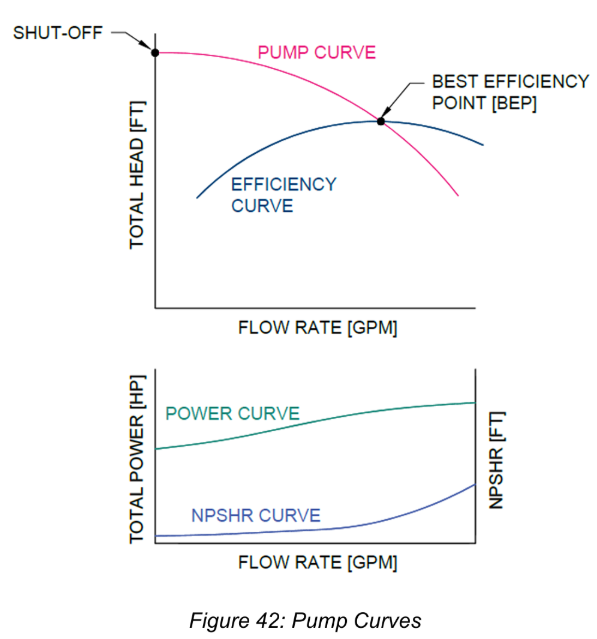
104
Pump System Curve
based on piping system (pipes, fittings, valves, and equipment) that the pump will be connected to; static pressure translates curve up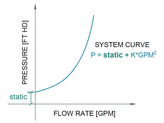
105
Operation point of pump
intersection of system and pump curve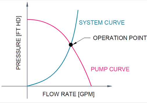
106
Pumps in parallel
produce flow equal to the sum of the flow of each individual pump at every pressure point; move right along flow rate axis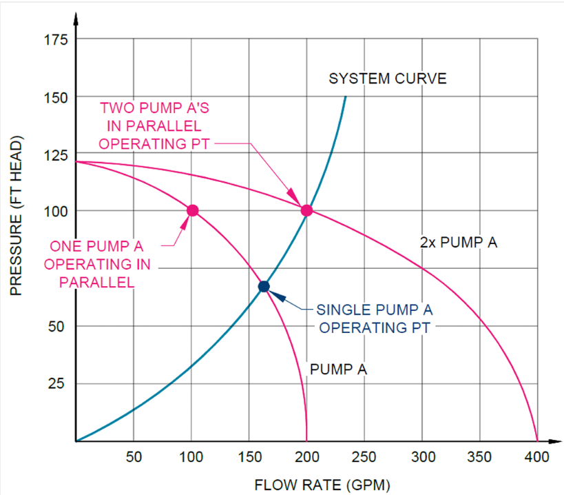
107
Pump in series
sum pressures of each pump, while flow remains unchanged; move directly up the pressure axis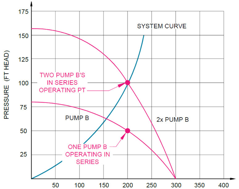
108
Throttling (pump/fan) flow rate
reduces flow by closing valve/damper, same power. Adds pressure to system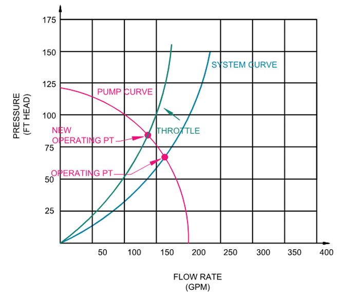
109
Pumps with VFD
reduces flow by reducing frequency -> reducing RPM and power of motor. RPM changes so pump curve changes, parallel to old curve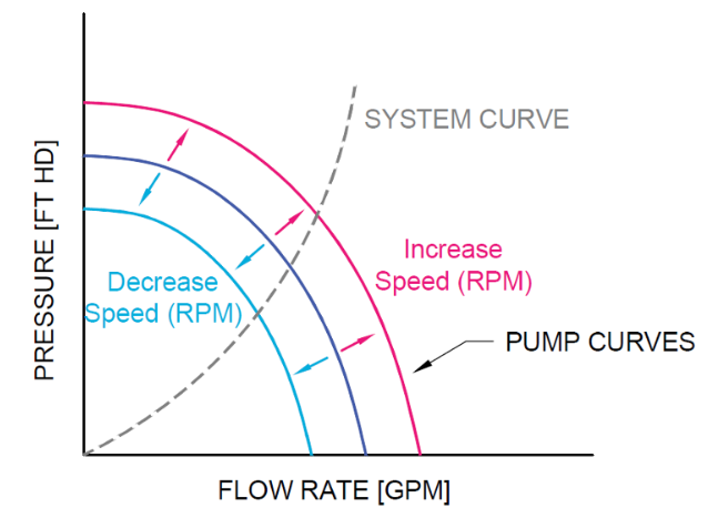
110
Net positive suction head available
1. Open system - $NPSHA=P_{abs} \pm P_{elev} - P_{fric} - P_{vapor}$
2. Closed system - $NPSHA=P_{gauge}+P_{velocity}-P_{vapor}$
2. Closed system - $NPSHA=P_{gauge}+P_{velocity}-P_{vapor}$
111
psi to ft head conversion
1 psi = 2.31 ft/SG (in handbook)
112
2.31 derivation
$1 psi = \frac{144~\frac {in^2}{ft^2}}{62.4~\frac{lb}{ft^3}} = ft~head $
113
velocity head (pumps)
$h_{P_{velocity}}=\frac{v^2}{2g}~[ft~head]$
114
Cavitation
static pressure of a liquid reduces to below the liquid's vapor pressure, leading to the formation of small vapor-filled cavities in the liquid. When subjected to higher pressure, these cavities, called "bubbles" or "voids", collapse and can generate shock waves that may damage machinery and piping
115
Fan Curve
Should operate within the stable region, as within the unstable region a given pressure value can have multiple CFMs; less change in CFM per change in pressure in stable region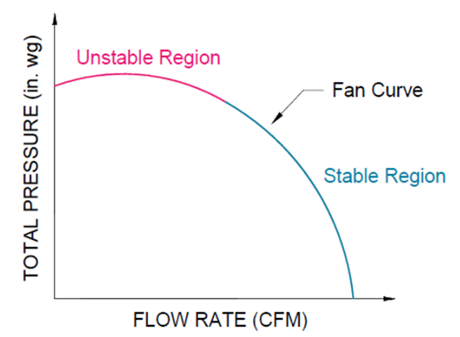
116
(Fan) system resistance curve
summation of all friction losses in the ducting system at varying CFMs; intersection of fan curve and resistance curve is operating point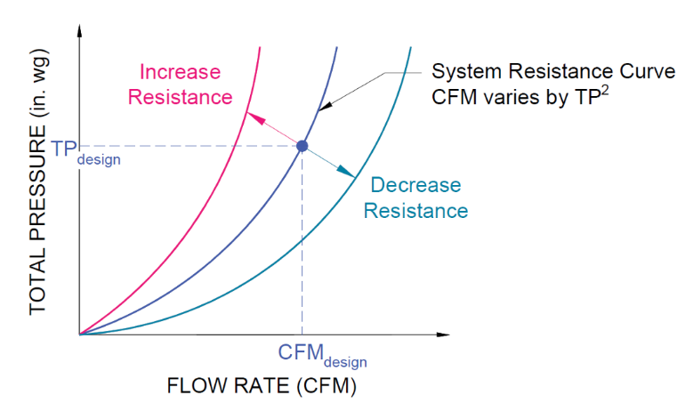
117
Explain these curves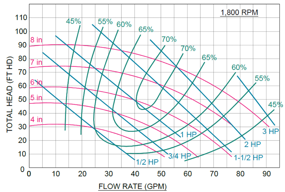
1. Red curves show impeller diameters and pressure at varying flow rates
2. Intersection of red curve and blue horsepower curve show horsepower required at operating point
3. Intersection of red and green curve show efficiency at operating point
2. Intersection of red curve and blue horsepower curve show horsepower required at operating point
3. Intersection of red and green curve show efficiency at operating point
118
Valve function
maintain a set pressure or flow
119
Valve types
globe valve - consists of a plug and a seat, where the plug is raised/lowered to increase/decrease flow
ball valve - ball in center of valve can be turned to enlarge or shrink the opening; opening is perpendicular to direction of flow when valve closed
butterfly valve - disc in the center of the valve that can be swung open and closed
ball valve - ball in center of valve can be turned to enlarge or shrink the opening; opening is perpendicular to direction of flow when valve closed
butterfly valve - disc in the center of the valve that can be swung open and closed
120
Valve authority
Relationship between flow rate and % open/close status of valve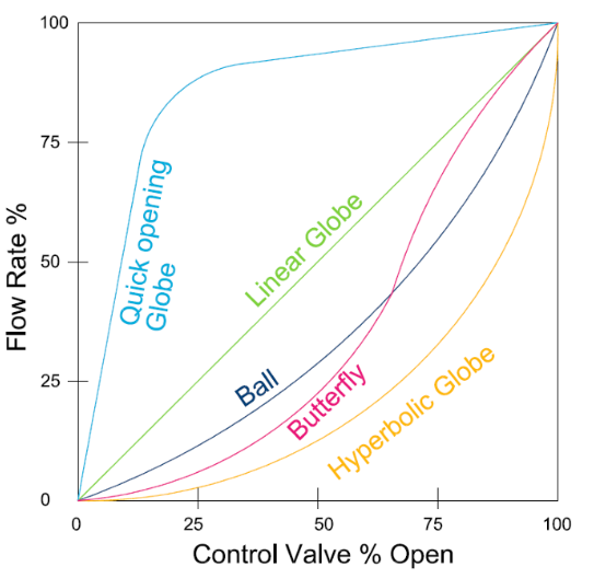
121
Valve coefficient
flow rate through valve in one minute at 1 psi; $C_{v}=\frac{Q}{\sqrt{ \Delta P}}$
122
Sizing valves for gases
Equation valid only when change in pressure across valve much less than operating pressure:
$Q~[scfh]=59.64*C_{v}*P_{operating}\sqrt{ \frac{\Delta P}{P_{operating}} }\sqrt{ \frac{520}{SG*T} }$
scfh = standard cubic feet per hour
T = absolute temperature (Rankine)
$Q~[scfh]=59.64*C_{v}*P_{operating}\sqrt{ \frac{\Delta P}{P_{operating}} }\sqrt{ \frac{520}{SG*T} }$
scfh = standard cubic feet per hour
T = absolute temperature (Rankine)
123
Critical Point (valves)
point where flow rate does not change no matter %open/close of valve
124
Control Dampers
control flow of air by modulating or two-position control, open/close
125
Damper Authority
Determines controllability of the damper; lower the value the less control at higher percentages of max airflow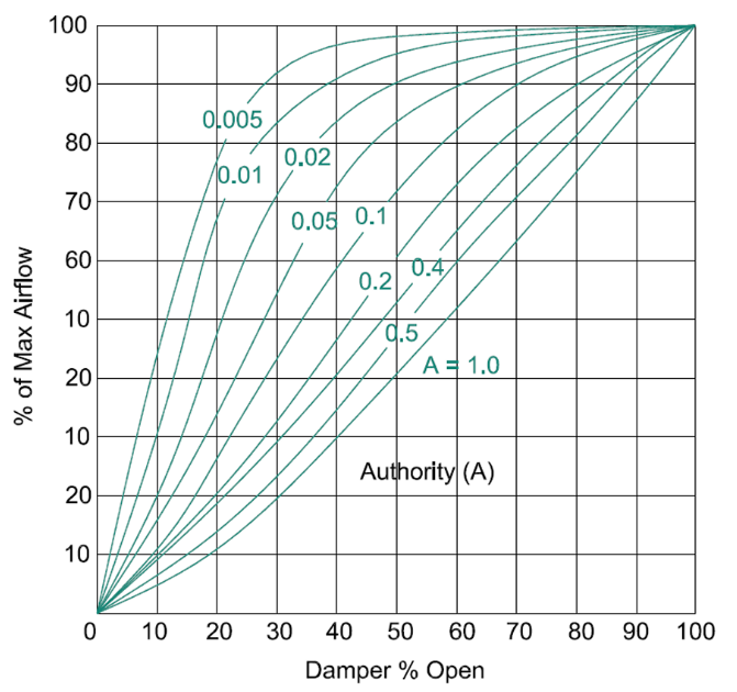
126
How is damper authority determined
dividing pressure drop through damper when open by total pressure drop through ducting (only includes ducting affected by the damper)
127
GWP
Global warming potential; reference point is $CO_{2}=1$
128
ODP
Ozone depleting potential; reference point is CFC-11 = 1
129
Refrigerant types
HCs - hydrocarbons
CFCs - chlorofluorocarbons
HCFCs - hydrochlorofluorocarbons
HFCs - hydrofluorocarbons
HFOs - Hydrofluoroolefins
CFCs - chlorofluorocarbons
HCFCs - hydrochlorofluorocarbons
HFCs - hydrofluorocarbons
HFOs - Hydrofluoroolefins
130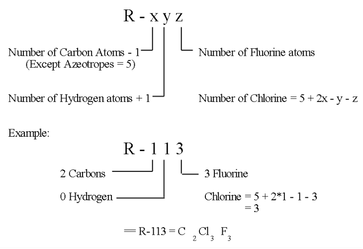
How are refrigerants classified
131
Name some CFCs
R-12,R-11; contains ozone depleting chlorine and high GWP; phased out in '95
132
Name some HCFCs
R-22,R142B; containes ozone depleting chlorine, high GWP; phasing out
133
Name some HFCs
R-134a,410A,32; ODP=0 but high GWP
134
Name some HFOs
HFO-1234yf; ODP=0 and very low GWP; next gen refrigerants
135
Refrigeration cycle components
Expansion valve, accumulator, filter, oil separator, hot gas bypass valve, receiver, filter/dryer, solenoid valve, sight glass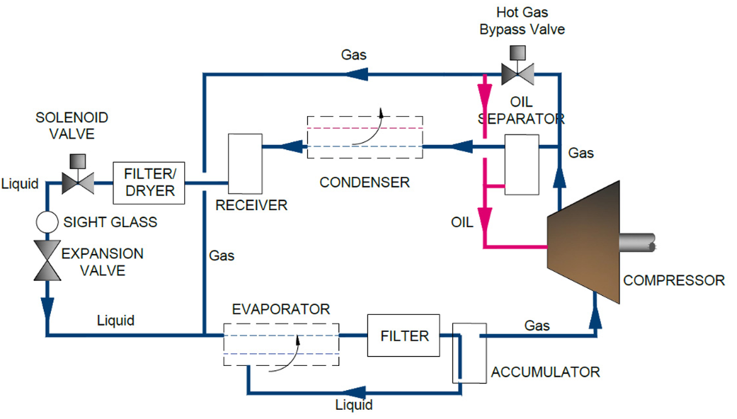
136
Accumulator
suction side of compressor after evaporator; accumulates excess liquid from evaporator that can damage compressor
137
Filter
placed at evaporator exit; prevents contaminants from entering the compressor
138
Oil separator
high pressure side of compressor - removes oil from refrigerant stream collected from oil seals/lubrication to ensure high heat transfer from refrigerant
139
Hot gas bypass valve
controlled by compressor inlet temperature; if evaporator temperature too cold, hot gas bypass the condenser and sent to the evaporator to create a false load to prevent frost
140
Receiver
after condensor; collects all the refrigerant liquid
141
Filter/Dryer
before expansion valve; protects expansion valve by removing contaminants and water moisture that could freeze the expansion valve (expansion valve lowers pressure to turn refrigerant to gas, but could freeze water as well if present)
142
Solenoid valve
after filter/dryer and interlocked with compressor; shut-off and open flow through system; when compressor shuts off and solenoid valve closes, separation between high pressure (condenser) and low pressure (evaporator) side
143
Sight glass
close to expansion valve - diagnostic tool to see refrigerant quality entering the expansion valve; check if refrigerant is liquid or gas and if frost or moisture forming
144
Supply air system components
air handling unit, supply ducting, dampers, terminal units, diffusers
145
Equivalent diameters
- Use to convert rectangular ducting to equivalent circle diameter; equations in handbook
- Hydraulic diameter for flow
- Equivalent diameter for duct air flow
- Hydraulic diameter for flow
- Equivalent diameter for duct air flow
146
Air handling unit (AHU)
Fan with cooling/heating cools, where exhaust air is replaced with new outside air
147
AHU components
(in order)
1. Mixing box - mixes correct amounts of outside air with return air using dampers
2. Air filter - protects following devices and keeps them clean
3. Heating and/or cooling coil - conditions air to correct leaving temperature
4. humidifer/dehumidifier - condition air to correct leaving humidity
5. Fan - provided ahead or behind devices depending on design; if last draw-thru, if first blow-thru
6. Energy recovery device - placed if applicable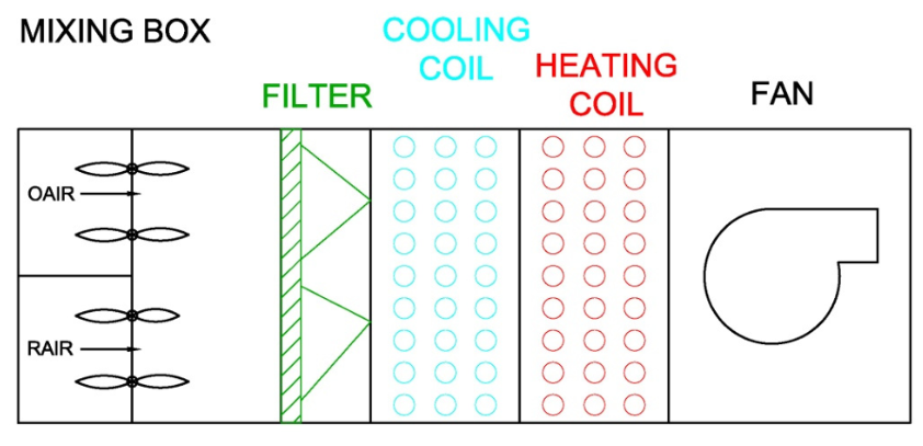
1. Mixing box - mixes correct amounts of outside air with return air using dampers
2. Air filter - protects following devices and keeps them clean
3. Heating and/or cooling coil - conditions air to correct leaving temperature
4. humidifer/dehumidifier - condition air to correct leaving humidity
5. Fan - provided ahead or behind devices depending on design; if last draw-thru, if first blow-thru
6. Energy recovery device - placed if applicable
148
Terminal unit
controls amount and conditions of air distributed to specific space, e.g. VAVs
149
Diffusers
control the way air distributed throughout the space; maintain minimum air velocity
150
Diffuser selection criteria
noise criteria, throw, velocity
151
ADPI
Air diffusion performance index - statistical percentage of points when measured uniformly within space whose draft velocities and temperatures fall within comfort criteria; <80 acceptable
152
How to read diffuser table
1-4-way signal how many directions you can throw the air out
numbers in column corresopnd to terminal velocities 150, 100, and 50 ft/min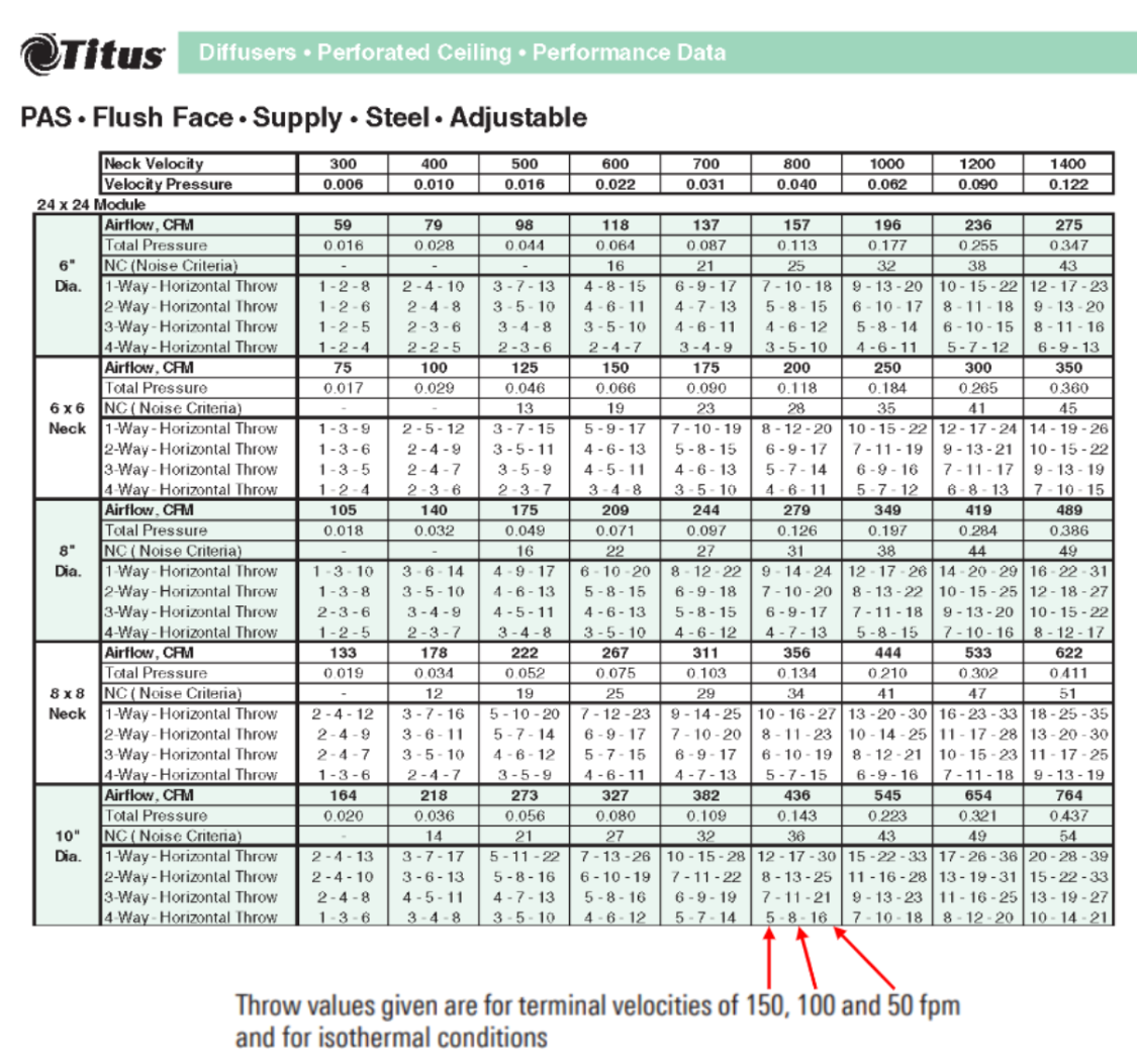
numbers in column corresopnd to terminal velocities 150, 100, and 50 ft/min
153
Constant volume system
- fans at AHU either on or off
- manual balancing dampers adjusted to supply a set airflow rate through diffuser based on max design conditions
- minimal controls for only one temperature zone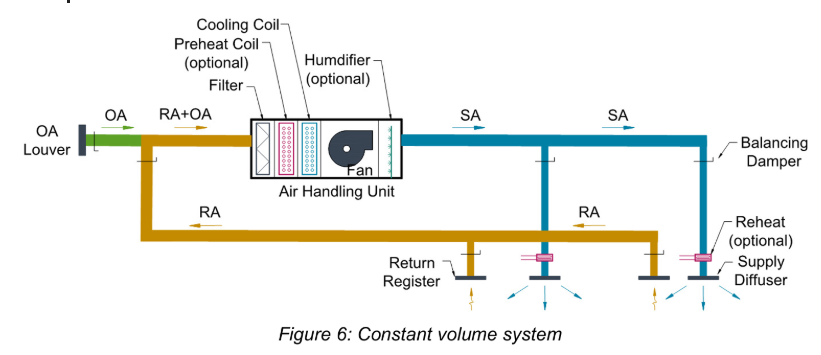
- manual balancing dampers adjusted to supply a set airflow rate through diffuser based on max design conditions
- minimal controls for only one temperature zone
154
Constant volume with reheat
heating coil installed in-line with duct to provide sensible heating; only allowed in specific scenarios:
1. One constant volume AH serves multiple rooms with different cooling schedule, but only one space thermostat to control fan; use reheat for more control
2. Reheat coil used to add load to prevent overcooling
1. One constant volume AH serves multiple rooms with different cooling schedule, but only one space thermostat to control fan; use reheat for more control
2. Reheat coil used to add load to prevent overcooling
155
Variable volume system
adds variable frequency drive (VFD) to fan in AHU and VAV boxes in supply air branches to adjust airflow based on cooling demands; reheat included if minimum airflow high enough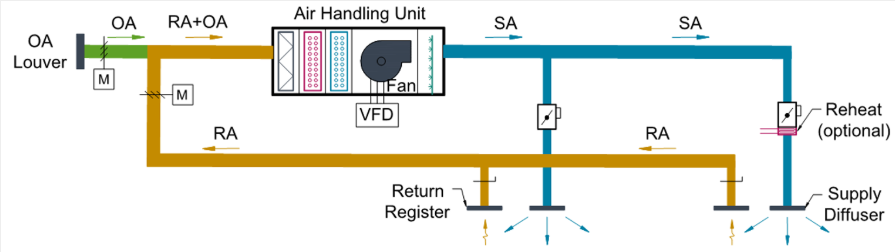
156
Dual duct system
one duct supplies hot air and other supplies cold air; dual duct VAV boxes connect to both air supplies so can mix in varying proportions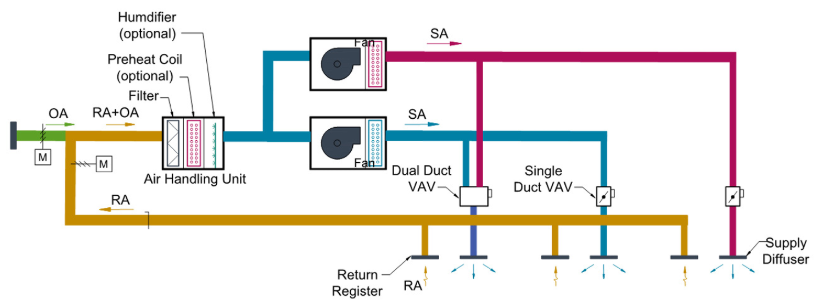
157
System controls of variable volume systems
- temperature sensor connect to VAV box controller and modulates damper to adjust cool air flow as needed
- when damper at min position, reheat has override; if open then damper has primary control
- pressure sensor ~2/3rds down the main duct branch to maintain system pressure and airflow rate
- track dampers used to verify sufficient outside air supply (or DOAS used)
- when damper at min position, reheat has override; if open then damper has primary control
- pressure sensor ~2/3rds down the main duct branch to maintain system pressure and airflow rate
- track dampers used to verify sufficient outside air supply (or DOAS used)
158
Convert GPM to CFS
$GPM*{\frac{1}{448.83}=ft^3}/s$
159
Anchors
supports that restrict movement of pipe in all three dimensions
160
L-bend, Z-bend, U-bend parameters
Equations found in handbook for calculating length of these bends to account for stresses
161
Air cooled, constant flow chilled water system
rejects heat to ambient air, so piping transports CHWS to air handlers/fan coils units; 3-way valves used to supply CHW to air handler or bypasses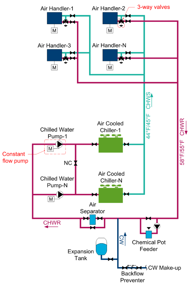
162
Water cooled, constant flow chilled water system
rejects heat to water which is brought to cooling tower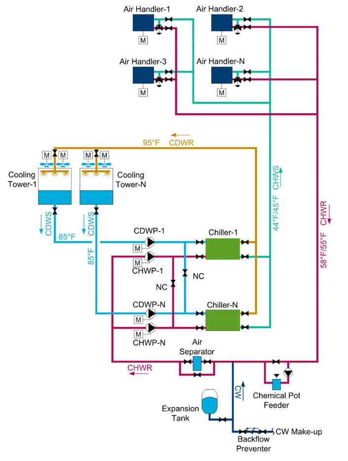
163
Variable-primary chilled water flow
variable speed pumps to distribute chilled water through a single loop between chiller and air handler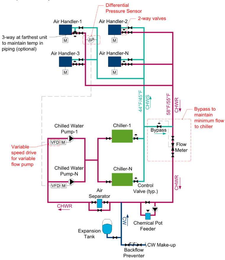
164
Primary-secondary chilled water-flow
two chilled water loops; primary loop circulates CHW through the chiller, secondary loop circulates CHW to air handlers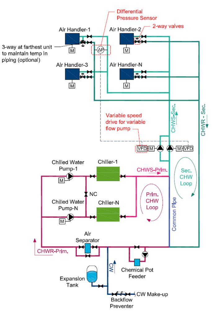
165
Direct-return
supplies and returns CHW in the most direct path, where the first AHU to receive and return CHW is closest to the chiller and the last AHU is farthest from the chiller (pressure drop needs to be accounted for from start to end via balancing)
166
Reverse-return
equalizes pressure throughout the loop by supplying the AHU closest to the chiller with CHW first, but the last unit to return
167
Dual temperature system
distributes both CHW and HW using different piping configurations (two pipe, four pipe, four pipe separate)
168
Longest length method
1.convert equipment Btuh value to cubic feet/hour of gas flow using either the HHV (if equipment is condensing) or LHV (if equipment not condensing) of fuel
2. find length of piping from delivery point to most remote outlet
3. Use natural gas pipe sizing table in handbook to get maximum CFH for each pipe size
2. find length of piping from delivery point to most remote outlet
3. Use natural gas pipe sizing table in handbook to get maximum CFH for each pipe size
169
Branch length method
1. convert equipment Btuh value to cubic feet/hour of gas flow using either the HHV (if equipment is condensing) or LHV (if equipment not condensing) of fuel
2. for each branch pipe section, take gas flow rate and the total length from that pipe section to the starting point (including length of pipe section too)
3. Use natural gas pipe sizing table in handbook to get maximum CFH for each pipe size
2. for each branch pipe section, take gas flow rate and the total length from that pipe section to the starting point (including length of pipe section too)
3. Use natural gas pipe sizing table in handbook to get maximum CFH for each pipe size
170
Sizing steam piping
Use steam pressure drop through piping table in handbook
171
Boiler steam system
Efficiency = change in enthalpy between steam and feedbwater over input energy from fuel
$\epsilon_{boiler}=\frac{\dot{m}_{water}*(h_{steam}-h_{feedwater})}{\dot{m}_{fuel}*HHV}$
$\epsilon_{boiler}=\frac{\dot{m}_{water}*(h_{steam}-h_{feedwater})}{\dot{m}_{fuel}*HHV}$
172
Wrap-around Heat Pipe
precool warm humid air by transferring heat to exiting cool supply air; typically used in warm humid climates in spaces with high outside air requirements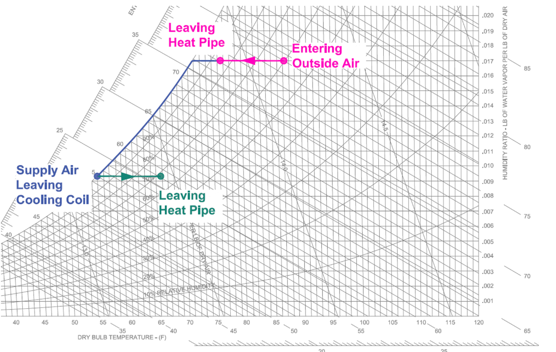
173
Run-around loop
two heat exchange coils connected by piping, a fluid, and a pump; heat transfer fluid pumped between two coils to transfer heat from one air stream to another
174
Air-Side Economizer
two sets of dampers, where one controls the amount of return air directed either to exhaust or back to the AH and another set controls amount of outside air routed to AH
175
Gain
ratio of change in output signal to change in input signal
176
Chilled water reset
Slowly increase chilled water temperature as load conditions fall (based on return air or outside air)
177
Supply air reset
Slowly increase supply air temperature if return air conditions or outside air conditions are met.
178
Temperature reset
temperature setpoint modulated by control system to match load of the system
179
Economizer
control system controls OA and RA dampers and an exhaust air fan on an AH to use less energy
180
ASHRAE 15
Safety Standard for Refrigeration Systems - Lists allowable refrigerant quantities per room volume and other safety considerations; has safety groups for each refrigerant 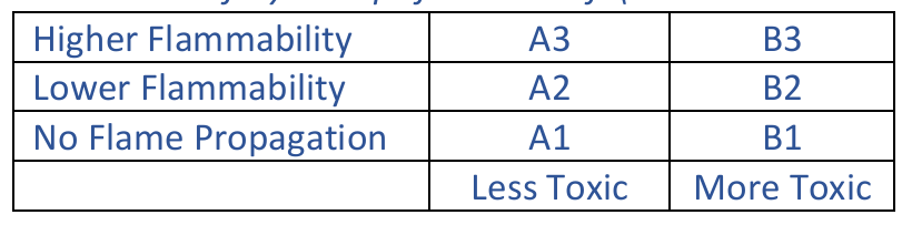
181
Required exhaust to evacuate refrigerant from space
$Q~[CFM]=100G^{0.5}$, where G=max lbs of refrigerant
182
ASHRAE 34
Safety Class of Refrigerants - Lists refrigerant safety groups, concentration limits, other refrigerant info
183
OEL
occupational exposure limit - concentration of refrigerant a person can withstand for a certain amount of time (~15 minutes)
184
LFL
lower flammability limit - lowest concentration (density) of refrigerant in air that can ignite at certain temperature (140F) and pressure (atm)
185
ASHRAE 55
Thermal Environment for Human Occupancy - Human comfort limits: draft, temperature, clothing 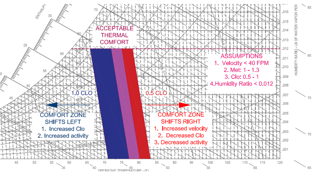
186
ASHRAE 62.1
Ventilation for acceptable Indoor Quality - establishes minimum qualities of fresh air through different types of occupied space to limit recirculation
187
ASHRAE 62.1 air classes
- Class 1 - low contaminant concentration (RA from offices, lobbies, libraries)
- Class 2 - moderate contaminant concentration (RA from art classrooms, nail salons, toilets, etc)
- Class 3 - significant contaminant concentration (RA from mechanical rooms, laundry rooms)
- Class 4 - highly objective fumes, dangerous particles, gases (RA from labs and chemical storage)
- Class 2 - moderate contaminant concentration (RA from art classrooms, nail salons, toilets, etc)
- Class 3 - significant contaminant concentration (RA from mechanical rooms, laundry rooms)
- Class 4 - highly objective fumes, dangerous particles, gases (RA from labs and chemical storage)
188
ASHRAE 62.2
Ventilation for Indoor Air Quality in Low Rise Residential
189
ASHRAE 90.1
Energy Standards for Buildings Except Low Rise Residential Buildings - minimum level of energy efficiency for HVAC systems and other building systems
190
ASHRAE 90.2
Energy Standard for low rise residential
191
ASHRAE 189.1
Standard for High-Performance Green Building, except Low Rise Residential - More stringent requirements than ASHRAE 90.1
192
NFPA 90A
Standard for the Installation of Air-Conditioning and Ventilating Systems - requirements for AC and ventilating equipment w.r.t fire protection
193
Smoke index
measure of smoke concentration of a material when it is burning; max allowed is 50
194
Smoke damper requirement
smoke damper required at all smoke barriers and should be activated automatically
195
Flame spread rating
how well a material burns and spreads a fire; maximum allowed is 25
196
Fire damper requirement
fire dampers required at all fire rated walls or partitions of 2 hours or more
197
NFPA 90B
Standard for the Installation of Warm Air Heating and Air-Conditioning Systems - provides requirements for ducts, heating panels, boilers, etc.
198
NFPA 96
Standards for Ventilation Control and Fire Protection for Commercial Cooking Operations
199
Montreal Protocol
plan for phasing out ozone depleting substances like CFC's and HCFC's
200
Minimum fresh air flow rate
Definedi n ASHRAE 62.1: $(min)~Fresh~air~flow~rate~(CFM)=R_{p}*(\#~of~people)+R_{A}*(Area)$
- R_P=people fresh air rate (CFM/person)
- R_A=area fresh air rate (CFM/Area)
- R_P=people fresh air rate (CFM/person)
- R_A=area fresh air rate (CFM/Area)
201
MERV
minimum efficiency reporting value for air filters - MERV-6 minimum
202
Vibration control
properly isolate or dampen moving parts to avoid damaging equipment and supporting structures
203
Vibration isolator selection process
1. Find disturbing vibration frequency (frequency the equipment is vibrating)
- fans, pumps, motors have frequency equal to their RPM (e.g. 1800 RPM * (1 min/60 s) = 30 hz)
- find and use lowest frequency if multiple, since it'll also isolate higher frequencies
2. Choose transmissibility of vibration isolator (amount of vibrations transmitted through isolation system)
$Isolation (\%)=100-Transmissibility (\%)$
3. Find natural frequency of vibration isolator required to achieve this transmissibility
4. Use required natural frequency to select vibration isolator
- consider support weight and deflection amount as well
- fans, pumps, motors have frequency equal to their RPM (e.g. 1800 RPM * (1 min/60 s) = 30 hz)
- find and use lowest frequency if multiple, since it'll also isolate higher frequencies
2. Choose transmissibility of vibration isolator (amount of vibrations transmitted through isolation system)
$Isolation (\%)=100-Transmissibility (\%)$
3. Find natural frequency of vibration isolator required to achieve this transmissibility
4. Use required natural frequency to select vibration isolator
- consider support weight and deflection amount as well
204
Relation between natural, disturbing frequency and transmission
The greater the ratio of $\frac{f_{d}}{f_{n}} > 1.4$, the greater the attenuation of transmissibility (decreases with square of frequency), i.e. vibration isolation improves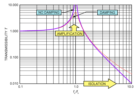
205
Base/Isolator types
Use selection guide for vibration isolation table in handbook
206
Sources of noise in HVAC
HVAC equipment, air turbulence
207
Sound power
"Heat source strength": $dB=10\log\left( \frac{W}{1*10^{-12}} \right)$
208
Sound pressure
"Resulting temperature": $dB=20\log\left( \frac{x~Pa}{20*10^{-6}~Pa} \right)$
209
Sound power and pressure relationship
$Sound~Power=Sound~Pressure+10\log\left( \frac{4\pi r^2}{A_{0}} \right)$
r = distance away from equipment
A0 = reference area (typically 1 m^2 or 1 ft^2)
r = distance away from equipment
A0 = reference area (typically 1 m^2 or 1 ft^2)
210
Sound table ratings
provide sound levels at range of frequencies
211
A-weighting (DBA)
give sound levels at lower frequencies a lower rating since they're not as easily heard by the ear
212
Total sound value
$L_{A}=10*\log(10^{DBA_{1}/10}+10^{DBA_{2}/10}+\dots)$; can also be used to combined multiple sources of noise
213
NC Rating
Room or space must be lower than all points of a given NC curve to meet that NC rating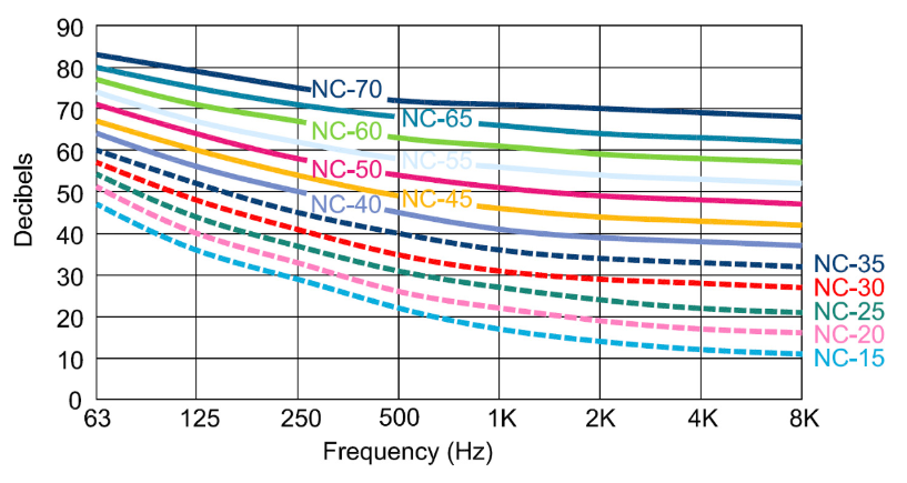
214
Duct insertion loss
Use duct insertion loss table in handbook to calculate sound power loss over duct lengths
215
Sound relation to distance
Sound reduces in proption to distance squared
216
Indoor turbulence sound calculations
primarily based on velocity; noise increases with turbulence and exacerbated by elbows, expansions, contractions that cause less smooth flow